Thanx.
when sourcing the 2SJ74 , what Idss should i go for?
it seams like +10ma are easyer to get.
Per
when sourcing the 2SJ74 , what Idss should i go for?
it seams like +10ma are easyer to get.
Per
It makes little difference (although 8mA is design center) - the CCS will make the Jfet current flow stable. 10mA will be fine.
Matched is very important.
Matched is very important.
What a day!
My friend and I put the Aleph J components into the chassis and wired everything up. We powered up first time with a Variac and got a horrible buzzing from the power transformer at 50V. Long story short, I am a tube guy and NEVER saw a power transformer with different color wires for each secondary. Oops! Hence the burnt insulation on the star ground wires.
Once we got that sorted out, we could only get one channel to adjust offset correctly and the other was at the negative rail. Thanks to 6L6, I checked the bad board and found Q2 was installed backwards.
With the amp warmed up, offset nulled and bias set, I hooked it up for the first time. I was impressed with how quite it was and could hear the JFETs hissing and crackling through my 102dB Cornwalls. The initial impression is very good. The imaging and detail is better than my current "reference amp" with is an RH84SE Rev2. The bottom end is much tighter and detailed, midrange is akin to the "tube" sound I am used to but top end is a bit veiled. Detail is there but on Percussion Fantasia's Canon in D I am missing the mallet impact with the xylophones that I get with the RH84SE. I am hoping this is part of the break-in and will open-up over time. Otherwise I will be capacitor rolling C1. I am also running this on a "low output" Foreplay pre-amp. I am building a DCB1 also, so maybe that will help as well.
I am waiting for fuse holders for my IEC inlets so I can finish up the AC wiring and then clean-up all of the wiring. I may also clip out all of the LEDs and put a single power LED in the faceplate.
Overall, VERY impressed! I would say, despite the top end, this is the best amplifier I have heard in my system and just about the best amplifier I have heard period. Mind you I am a tube guy and do not like the "solid state" sound of which this is not. The only other solid state I ever liked was my old Yamaha M4. 🙂
Thanks for everyone's hard work on the PCB's, and the build guides! The only suggestion would be to have a document that contains everything:
- Schematic
- BOM
- Build steps (I missed the pre-setting of the pots)
- Initial power-up & setting offset/bias
Attachments
Last edited:
The only suggestion would be to have a document that contains everything:
- Schematic
- BOM
- Build steps (I missed the pre-setting of the pots)
- Initial power-up & setting offset/bias
Have you seen post #1 and #2 of this very thread? It has all that you mention.
😀 😀 😀
Have you seen post #1 and #2 of this very thread? It has all that you mention.
😀 😀 😀
It does and it doesn't. The pictures don't match the descriptions and the order jumps a bit. Sorry ... not trying to being nit-picky. The issues I ran into during the build were:
1. The note to pre-set the pots was too late in the posts or I somehow I completely missed it.
2. The BOM calls for a 2K pot for R8 but the posts mention nothing about a pot or how to set it. The BOM should say a 1K resistor.
3. BOM is confusing with R6/R30 or Jumper ... did not know which to choose with the exception of J1 & J2 which had a note.
4. No mention of matching tolerance required on FETs or matching/ranking of JFETs without digging.
5. Power supply is not covered at all in the first several posts.
6. No mention on SE input wiring in the first several posts.
The answers to most I found after digging through the thread but they were not obvious. This is my first solid state build and I was rather confused vs. other DIY equipment (and instructions) that I have built.
The other issue was the silkscreen on the PCB does not match the schematic 1:1 (i.e. R27, R27', R27A, R27B, etc.) That and the silk on the Universal Power Supply board is non-conventional too (i.e. AC+ vs. ST_IN1/D+1?) and I ended up hooking it up backwards the first time ... DOH! Good thing it is almost a palindrome. 😉
Not sure about you, but when I am soldering at the workbench or setting up in my music room, I prefer paper so I can write down notes, etc. Maybe I am just weird. 😛
... Just my observations having just gone through the process and fresh in my mind ... not trying to ruffle any feathers! FWIW, I have written several "Tech Notes" for Engineering Software in the past and am just used to "Step 1, Step 2, ..." for us lesser edumacated K.I.S.S. folks. 😀
I1. The note to pre-set the pots was too late in the posts or I somehow I completely missed it.
I would hope that people would read the documentation first and completely before construction. 🙂 🙂 🙂
I agree. This is exactly why I don't like working from BOM. They get stale very fast. (but they are a necessary evil for understanding what parts to order)2. The BOM calls for a 2K pot for R8 but the posts mention nothing about a pot or how to set it. The BOM should say a 1K resistor.
See above.3. BOM is confusing with R6/R30 or Jumper ... did not know which to choose with the exception of J1 & J2 which had a note.
Good point.4. No mention of matching tolerance required on FETs or matching/ranking of JFETs without digging.
??? I'm positive there is PSU information in post 1.5. Power supply is not covered at all in the first several posts.
It's shown in post 3, but not specifically pointed out.6. No mention on SE input wiring in the first several posts.
These are not instructions. This is not a procedure on how to build an AJ with specific parts. It is a guide.This is my first solid state build and I was rather confused vs. other DIY equipment (and instructions) that I have built.
It's awfully close, but fair point.The other issue was the silkscreen on the PCB does not match the schematic 1:1 (i.e. R27, R27', R27A, R27B, etc.)
Sometimes things need to be a bit vague to make them appropriate for more projects. But again, fair point.That and the silk on the Universal Power Supply board is non-conventional too (i.e. AC+ vs. ST_IN1/D+1?) and I ended up hooking it up backwards the first time ... DOH! Good thing it is almost a palindrome. 😉
Not weird at all. I always print out what documentation I can find about these projects.Not sure about you, but when I am soldering at the workbench or setting up in my music room, I prefer paper so I can write down notes, etc. Maybe I am just weird. 😛
Not a bad idea, however there is a lot of variability on how people build these, including specific parts choices and availability, PSU design and parts, PCB, etc... so there is no pressing need to make a step-by-step guide detailed down to the last screw turn and solder joint as most people will not have the exact same pile of parts to start with. Hence why a guide with lots of illustrations and example is as good as I can make.am just used to "Step 1, Step 2, ..." for us lesser edumacated K.I.S.S. folks. 😀
BTW, this is a volunteer effort for me.
Last edited:
Your guides and this thread were invaluable! Hey ... the amp is built and functioning beautifully right now after all ...
... some of my issues may have been attributed to the consumption of "Chocolade Koffie Stout" as well.
... some of my issues may have been attributed to the consumption of "Chocolade Koffie Stout" as well.
Here is a question for those that built this with the Universal Power Supply boards. When I shut the amp off, the V- LED stays on for a while as the caps bleed off but the V+ LED goes out almost instantaneously.
Did I fry my PS caps when I hooked the secondaries up wrong?
What do your LED's do when you power down?
Did I fry my PS caps when I hooked the secondaries up wrong?
What do your LED's do when you power down?
I'm new to the Pass stuff so forgive the question if it's stupid. Is the Aleph-J an "X" design or better put, does it have any S/N circuit cancellation? To me it just looks like an Aleph with a JFET front end.
....... To me it just looks like an Aleph with a JFET front end.
exactly .
To me it just looks like a decent amp .

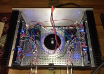
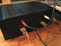
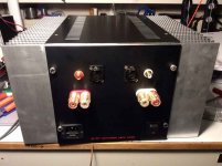
Here are some final build pics for y'all to enjoy! 😀
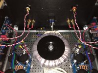
And one more question for the gurus ... when I had the transformer primary wire-nutted to an extension cord (without ground), the amp had NO hum! Now that I installed the IEC inlet, CL60's and AC line filter WITH a grounded IEC cable, I have a very slight hum. I need to go find my IEC that I have snapped the ground prong off of, but take a look at the pictures ... open to suggestions!
This is the most "engaging" amp I have built. Even more so than my RH84SE Rev2. Still would like the highs less rolled-off, so ordering a set of Mundorf EVO Silver Gold Oils ... hope that helps!
Attachments


use IEC without filter , be sure that each channel audio gnd is having own dedicated CL60 going to case/safety gnd
damn
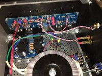
it seems that you have common PSU for both channels .......
put fat wire as bridge between main gnd points of two channel's pcbs
it seems that you have common PSU for both channels .......
put fat wire as bridge between main gnd points of two channel's pcbs
The green wire is tying GND together, so PSU is wired as bipolar... But I agree, a bigger wire there is a really good idea.
Isolating that wire from chassis with a CL-60 (as shown in the PSU diagram) will fix that. Your GND is currently at chassis (and therefore AC safety earth) potential.
when I had the transformer primary wire-nutted to an extension cord (without ground), the amp had NO hum! Now that I installed the IEC inlet, CL60's and AC line filter WITH a grounded IEC cable, I have a very slight hum.
Isolating that wire from chassis with a CL-60 (as shown in the PSU diagram) will fix that. Your GND is currently at chassis (and therefore AC safety earth) potential.
Last edited:
The green wire is pretty big (hard to tell in the pics). It is about as large as I can fit in the PCB holes.
Right now that wire ties to chassis and IEC inlet. Nelson shows isolating the DC GND from the chassis AC GND with a thermistor which I can try. What about leaving the DC GND connected to chassis and isolating from IEC inlet with thermistor? Will that negate the safety aspect?
The only things that changed between it being quiet and noisy are:
I have also tried an IEC with a snapped off GND pin and still has noise ... makes no sense since it was quiet before with the same chassis/GND wring. 😕
Right now that wire ties to chassis and IEC inlet. Nelson shows isolating the DC GND from the chassis AC GND with a thermistor which I can try. What about leaving the DC GND connected to chassis and isolating from IEC inlet with thermistor? Will that negate the safety aspect?
The only things that changed between it being quiet and noisy are:
- IEC cord with GND
- Thermistors on transformer primaries
- Cap across AC inlet
I have also tried an IEC with a snapped off GND pin and still has noise ... makes no sense since it was quiet before with the same chassis/GND wring. 😕
Last edited:
What about leaving the DC GND connected to chassis and isolating from IEC inlet with thermistor? Will that negate the safety aspect?
AC safety earth MUST touch the chassis unhindered. Power supply GND gets elevated off chassis by the thermistor.
Another dutch Aleph-J nears completion.
Received my panels this week, assembly can start this weekend !
Better and complete photo's will follow soon.
Regards,
Nick
Received my panels this week, assembly can start this weekend !
Better and complete photo's will follow soon.
Regards,
Nick
Attachments

Last edited:
- Home
- Amplifiers
- Pass Labs
- Aleph J illustrated build guide