I will go through the ground loops article.
I don’t have the 156B on hand, but I have literally dozens of the 154B. It is 3mH at 1.5 amps and .14 Ohms of resistance. Can I use one (or more of) these instead? Does a pair in parallel give me 1.5mH at .07 Ohms resistance and double the current capability? I can add two per rail for a total of four in the power supply. Is the 1.5 amp rating enough for the Aleph J? A single 154B would provide 3mH rather than the 1.5mH of two in parallel.
Each channel draws about 1.7A so a pair in parallel per rail should work. The slight overage in current through the chokes will lower the inductance a tiny bit but that shouldn't be a problem. The chokes are rated for 300 VDC so power dissipation should not be an issue.
Great. Does it make sense to add an LC to the power supply since I'll have the room?Each channel draws about 1.7A so a pair in parallel per rail should work. The slight overage in current through the chokes will lower the inductance a tiny bit but that shouldn't be a problem. The chokes are rated for 300 VDC so power dissipation should not be an issue.
What positions on the board should these be installed?I’d add those since you are in work mode anyways. 180-220R for example should do fine, if I remember correctly.
Hi folks... does anyone know where the BOM is for the Adelph J? I want to check if R14 is really 392 (3K9) as in the png schematic or as my calculation 391 (390R).
Thanks!
Thanks!
I don’t have the boards in front of me, but that should be in the J1 and J2 positions 🙂What positions on the board should these be installed?
https://diyaudiostore.com/products/aleph-jHi folks... does anyone know where the BOM is for the Adelph J? I want to check if R14 is really 392 (3K9) as in the png schematic or as my calculation 391 (390R).
Thanks!
Ok thanks Andy. Not sure if its me, but these links don't seem to want to work...
OK its me DOH! Thanks!Ok thanks Andy. Not sure if its me, but these links don't seem to want to work...

R14 is ~390R (with R13 ~220R). I think in this case 392 meant literally 392R and not 3K9 which is what is how the RN resistors are labelled.
Papa has mentioned in an aleph thread about optionally removing the current limiter:
https://www.diyaudio.com/community/threads/the-aleph-design-reloaded.267857/#post-4184920
Papa has mentioned in an aleph thread about optionally removing the current limiter:
https://www.diyaudio.com/community/threads/the-aleph-design-reloaded.267857/#post-4184920
Yes.Great. Does it make sense to add an LC to the power supply since I'll have the room?
Instead of paralleling the chokes, you can provide a LC section to the V+ and V- to each channel. This has the advantage of some isolation between channels.
Thanks. So split the V+ and V- rails with two chokes per rail, then a capacitor, and then to the boards as in the diagram? Is there a minimum amount of capacitance recommended for the final capacitance node in this case? I ask because while I have several different pairs of large value capacitors, I don’t have quads of as many types. From memory, the quads are 5500uF and 10000uF. Also, I have a few quads of much smaller value (100uF) film capacitors as well if that will work, and provide some advantage.Yes.
Instead of paralleling the chokes, you can provide a LC section to the V+ and V- to each channel. This has the advantage of some isolation between channels.
cap in parallel, not in series
except if your intention is to make The Muter instead of amplifier 🙂
except if your intention is to make The Muter instead of amplifier 🙂
What Zen Mod said. On V+, cap + to choke, cap - to Gnd. On V-, cap - to choke, cap + to Gnd.
If you have 10,000uF, use them.
Twist V+, V-, and Gnd together for each channel.
If you have 10,000uF, use them.
Twist V+, V-, and Gnd together for each channel.
Oops.cap in parallel, not in series
except if your intention is to make The Muter instead of amplifier 🙂
Thanks. Will do.What Zen Mod said. On V+, cap + to choke, cap - to Gnd. On V-, cap - to choke, cap + to Gnd.
If you have 10,000uF, use them.
Twist V+, V-, and Gnd together for each channel.
Yes.
Instead of paralleling the chokes, you can provide a LC section to the V+ and V- to each channel. This has the advantage of some isolation between channels.
Be sure what you are doing with your gnd. For example, with LC after CRC, you beed to consider moving your junction to the end of the supply. Follow the T, as suggested by boky, and cut a metal triangle to establish it, is one way of doing it.Thanks. Will do.
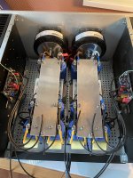
See the pics of my J earlier, and you’ll get the idea. Also, see Zen Mod’s blog. He hand built a few PSUs earlier, modelling this pretty much exactly 🙂
Make sure your gnd takeoffs are not in the middle of the junction between pos and neg halves, is the essence, and for 104db sens, make that point at the quietest part of the PSU. This can be other places than at the end, but the end is often close to the quietest part.
That said, it might work tapping the audio gnd off one of the cap joints. But it is seldom the most quiet place, though it can be quiet enough.
Remember/ collect your audio grounds to one point. I know you are allready accustomed to this thinking, I saw early on your perfect junction takeoff to chassis gnd 🙂
Edit: agree with Boky: the uni-PSU has a crappy gnd layout. This is your chance to remedy that 🙂
Attachments
Last edited:
I’m confused. Please explain what this means.Follow the T, as suggested by boky, and cut a metal triangle to establish it, is one way of doing it.
If I understand your post correctly, I need to take the main ground connection off the PSU board and move it to the new end of the power supply. Also, I need to remove all previous connections made between the halves of the existing PSU, and connect the augmented halves at the end of the PSU? This would make the final connection at the last set of four capacitors if I split the current supply off and feed two chokes as per my drawing. Is this correct?
Your photo looks great. It looks like the metal plate is used as the ground plane. Is this correct? How did you attach the caps to the chassis underneath? Where are the rectifiers?Be sure what you are doing with your gnd. For example, with LC after CRC, you beed to consider moving your junction to the end of the supply. Follow the T, as suggested by boky, and cut a metal triangle to establish it, is one way of doing it.
See the pics of my J earlier, and you’ll get the idea. Also, see Zen Mod’s blog. He hand built a few PSUs earlier, modelling this pretty much exactly 🙂
Make sure your gnd takeoffs are not in the middle of the junction between pos and neg halves, is the essence, and for 104db sens, make that point at the quietest part of the PSU. This can be other places than at the end, but the end is often close to the quietest part.
That said, it might work tapping the audio gnd off one of the cap joints. But it is seldom the most quiet place, though it can be quiet enough.
Remember/ collect your audio grounds to one point. I know you are allready accustomed to this thinking, I saw early on your perfect junction takeoff to chassis gnd 🙂
Edit: agree with Boky: the uni-PSU has a crappy gnd layout. This is your chance to remedy that 🙂
Last edited:
You can leave the existing power supply board as-is.
You can connect the chokes' wires for one channel to V+ and V-, add a Gnd wire and twist them together. Connect the other end of the chokes' V+ and V- to the capacitors, and connect the Gnd to the top of the Tee. The V+ and V- output wires are then connected to the capacitors and the Gnd wire is connected to the bottom of the tee. Twist the wires and route them to the amp board. Repeat for the other channel.
Note that the Tee need not be Tee shaped. The critical point is that the Gnd output is outside of the 0V region. A triangle or rectangle shape is ok.
Ground connection of bipolar supply capacitors - from Bonsai's Ground Loop article page 60:
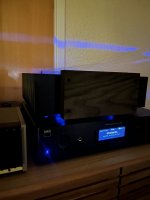
I’m still waiting for my 2nd smps. The sooner it gets here the better, the fan noise from keeping a single smps cool is really bugging me! Apparently it has arrived in the country so my amp will be dual mono fan free soon.
I put feet on my amp and also the extra powercon socket I will need.
I tried a wood face plate but don’t really like it. I will try something else soon.
My amp is still totally silent but I don’t have super sensitive speakers.
I put feet on my amp and also the extra powercon socket I will need.
I tried a wood face plate but don’t really like it. I will try something else soon.
My amp is still totally silent but I don’t have super sensitive speakers.
Attachments
- Home
- Amplifiers
- Pass Labs
- Aleph J illustrated build guide