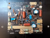
means - as long they're functional - use them

(if you find better ones later, replace them, then use first ones for something else)

(if you find better ones later, replace them, then use first ones for something else)
And continue the half-newbie questions, out of curiosity and for later reference, what is the bias current of the JFETs in the AJ? Can’t measure the drop, don’t have the circuit yet. This is prolly the moment you tell me to reread Ohms law and study some primary school maths…
Approximately 5mA, said Zen Mod:
Aleph J 2SJ74 Idss question
If you don't have the amplifier to measure, you can build it in LTSpice and measure it.
Aleph J 2SJ74 Idss question
If you don't have the amplifier to measure, you can build it in LTSpice and measure it.
Thank you, Ben! I read your’s and the other greedy boyz posts and am continuosly in awe, learning bit by bit. Please excuse me going the simple route of asking. I just wanted to know if my fets are usable or not before proceeding with the idea.
What do you guys think about the idea of BA-3 for woofers and AJ for mid and treble? I want sweet but still dynamic, punchy and with good transient response. And if possible, palpative, wide and deep. Tough demands, but call it the ultimate goal.might take a few years seing as I am on a building pause for dunno how long.
Cheers,
Andy
your thinking is good and intriguing
now, to solve intrigue - is that progress - for you , just build and try

now, to solve intrigue - is that progress - for you , just build and try

Both a compliment and some sarcasm from Mighty! Must mean the idea is worth at least a few mZM’s. BA-1 is pos phase, think I’ll go with AJ’s neg phase supernaturalness.
Last edited:
With correct speakers, still a wide range, either of these amps could do all of, or either roll you propose. The BA3 can be wonderful through the upper ranges, and the Aleph J is no single ended weakling, it has surprising power in the lower ranges.
Russellc
Russellc
Last edited:
or just swap speaker cables at one end or other.
Russellc
True true
With correct speakers, still a wide range, either of these amps could do all of, or either roll you propose. The BA3 can be wonderful through the upper ranges, and the Aleph J is no single ended weakling, it has surprising power in the lower ranges.
Russellc
Was thinking about asking you about your thoughts, I know you have both and have listened a bit to them. But if I go the OB route with an active crossover, I thought it best (or the only way?) to have two amps without the need for a crossover st the speakers. Still on the idea stage, so I am all ears!
Last edited:
When you power up the amp for the first time and proceed with the adjustments, do you need to 1) short the input and 2) put a dummy load at the output?
Let's resume the JZen journey...
As I'll do a CLC dual mono PSU, I needed a BIG cabinet for PCBs, Irons, Donuts, Life, the Universe and Everything....
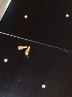
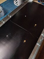
As Mighty ZM suggested, I bought a 4U/400 cabinet from the well known 'talian company. So, the first step will be the tapping for the M3 screws in heatsinks.
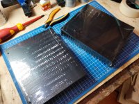
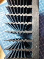
They're Biiiiiiiig!!
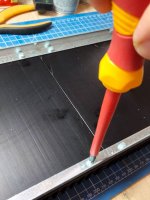
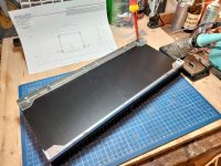
I have to fasten the brackets with 6 M4 screws


Some masking tape for the drawings
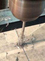
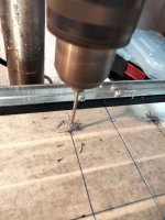
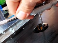
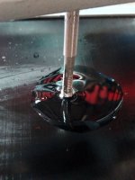
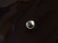
Drilling with 2,5mm bit and some cutting oil
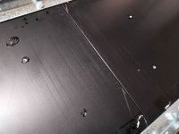
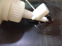
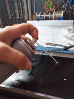
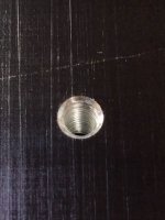
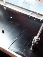
Now it's time for tapping...
As I'll do a CLC dual mono PSU, I needed a BIG cabinet for PCBs, Irons, Donuts, Life, the Universe and Everything....
As Mighty ZM suggested, I bought a 4U/400 cabinet from the well known 'talian company. So, the first step will be the tapping for the M3 screws in heatsinks.


They're Biiiiiiiig!!


I have to fasten the brackets with 6 M4 screws


Some masking tape for the drawings


Drilling with 2,5mm bit and some cutting oil


Now it's time for tapping...
Dear All,
finally I finished my building and just started testing.
The PSU seems correct: light bulb test OK, red and green leds switch on and I measure plus and minus 23V DC at capacitors output with 220 VAC at my main power input (I live in Europe).
I tested both my amp boards and things are not going as indicated by the building guide. First of all, when I switch-on the amp, the light bulb switches on and then quickly switches competely off instead of a lower level light.
The blue leds of the amp corretly swtich on and remain on; but when I measure VDC at input resistor as suggested in the guide to adjust BIAS, I measure 0mV in practice. Things do not change by adjusting R27 resistor (as suggested by the guide I make this test with a clean power wire, no more light bulb).
At AMP output (to be connected to the speakers) I measure 700mV on one channel and 400mV on the other one.
In addition I expected the heatsink to warm up but they remain cold.
Can you suggest me what is going on?
Thank you for the help
renato
- Home
- Amplifiers
- Pass Labs
- Aleph J illustrated build guide
