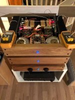
Nice work! Pardon my ignorance, but what are the four big coppery looking things in the back?
Thanx,
This Amp is the last in several "Pellesmil design" cabinets,
Oak and metal combined, and they all have my spesiffic footpring X 100mm high.
As i wanted to pack as much as possible capacitabce in the PS i needed to re-think the stacking of the capacitors,
With the inductors in place its wery close what this cabinet can carry.
As for your Q, the copper things are a cage to hold the no 2 bank of capacitors (8 + 8 3300uf ROE).
The room between the capacitors where then filled with silicone to hold them in place and reduce hamonics.
Im open for dicussion whether the silicone offers any sound benefits but it keeps me sleeping at night🙄
Attachments


Up and running part 3
Yes.
Solved all issues tonight🙂
For those of you that have Holton HPA-LSP-One Rev 5 - Loudspeaker Protection Boards:
It will only work if you tap the AC from the windings that supply the posetive rectefier.
In short, the voltage between the power GND and any of the AC lines shall be poseive not negative.
So.....
Yesterday at the workbench i adjusted the bias to 450mv and the temperature on the transistors where sniffing at 60deg C.
Today whitout lid it settles at 59/58deg C (R/L device temp) and 54/53deg C (R/L sink)
The sound is as i expected to hear from a good Class A amp, at first glance its nothing special, no bling no flexing no shouting, just music
and after an hour or so it crawls under my skin.
Love it.
Need to adjust my DPS tho, it has less gain than my Holton nxV300R2 so in my dual amp setup the sub is beating a lot of bass out in the room.
The 2,2mH inductors are not connected, will do that later.
Attachments
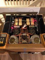
Holy crap! You have 2x 800VA power transformers!?!?
Exactly my reaction, but if that's what was on hand; why not?
The sound is as i expected to hear from a good Class A amp, at first glance its nothing special, no bling no flexing no shouting, just music
and after an hour or so it crawls under my skin.
Love it.
Well said, and congratulations

I have another, perhaps foolish, question to ask.
Looking at the 'Extreme_Boky ground mod' (post #4562 onward), could the resistor be substituted for a CL60?
It might be a bit physically cumbersome, but provides the necessary 10 ohm resistance and would better serve under a fault condition (post #4740) would it not?
Or am I overthinking this? (I haven't much else to do while waiting for parts!)
I spent some time thinking about the possible scenarios as well.... and ended up using a fusible 10ohm resistor.
Later on, I moved to a fully balanced config, and then grounded interconnects' shield straight to the chassis, as soon as it (the shield) entered the amplifier. Then I removed the resistors because the amp was quiet. Unfortunately, you can not do this with single-ended inputs...
Later on, I moved to a fully balanced config, and then grounded interconnects' shield straight to the chassis, as soon as it (the shield) entered the amplifier. Then I removed the resistors because the amp was quiet. Unfortunately, you can not do this with single-ended inputs...
Ah yes, I missed that you mentioned that in post #4740. I didn't know such a thing existed.
I suppose then the choice is between:
a) isolating the fault with a fusible resistor, or
b) hoping to allow the fault to escape to ground through a standard resistor or thermistor?
Do I recall correctly that your problem wasn't able to be cured by running the speaker return to the PSU ground?
I suppose then the choice is between:
a) isolating the fault with a fusible resistor, or
b) hoping to allow the fault to escape to ground through a standard resistor or thermistor?
Do I recall correctly that your problem wasn't able to be cured by running the speaker return to the PSU ground?
Option b) is not going to happen like you are predicting.... In the case of a catastrophic failure, where a potent + and - 24V DC supply is shorted to ground via a semiconductor and/or another component (resistor, or even a PCB track..) the fault current will cause a fire. The fault current will keep "escaping" until one of the series components burns out.
Option a) has a better chance of isolating the issue, because the fault current return to the ground, in such case (catastrophic failure), would cause the fusible resistor to open fairly quickly.
Hence the choice I made
Option a) has a better chance of isolating the issue, because the fault current return to the ground, in such case (catastrophic failure), would cause the fusible resistor to open fairly quickly.
Hence the choice I made
Last edited:
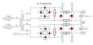
Hello experts! Can someone explain what capacitor C9 actually does (the blue one here)? Various earlier posts alternately describe it as a safety cap or a line filtering cap.
Also, some are telling me that the best practice is to use 3 CL60 thermistors, but I see only two attached to the AC in terminal block in this diagram. Where does the third one go? I assume all three same specs?
Thanks for any help!
Also, some are telling me that the best practice is to use 3 CL60 thermistors, but I see only two attached to the AC in terminal block in this diagram. Where does the third one go? I assume all three same specs?
Thanks for any help!
The blue cap is an EMI/RFI suppression cap.
The 3rd CL60 goes between chassis and PS ground. You can see it in the
PS schematics on the last page here:
http://www.firstwatt.com/pdf/prod_f5_man.pdf
The 3rd CL60 goes between chassis and PS ground. You can see it in the
PS schematics on the last page here:
http://www.firstwatt.com/pdf/prod_f5_man.pdf
800VA transformers are a bit excessive for a 25W amplifier.
YES, you will get definite returns by reducing the impedance of the PSU but beyond about 500VA and 100 000uF the returns will be virtually inaudible.
YES, you will get definite returns by reducing the impedance of the PSU but beyond about 500VA and 100 000uF the returns will be virtually inaudible.
I recently built the power supply for the Aleph J and assembled an annotated photograph for the critical connections.


I will trim the transformer primaries leads and secondaries leads once I have the amp assembled and can determine the optimal rotational position of the transformer for least noise from interference.
The photo below shows more detail in mounting the third CL-60 inrush limiter between the amplifier ground and the earth ground and chassis. I formed one of the leads of the CL-60 into a ring and soldered it to the ring terminal connector on the earth ground lead, and then bolted that to the chassis.

I followed Pechelman's recommendation on using the Simpson Strong-Tie A24 L-bracket. I little work on the drill press and some 6mm screws and Nylon lock-nuts made vertically mounting the transformer a breeze.

I double-checked all my connections and then used the dim bulb test on powering up the power supply. I got the momentary flash of the bulb, and there was no smoke, no sparks or any other drama. I measured -25V DC on the negative rail and +25V DC on the positive rail.
Good to go with mounting the Aleph J boards and wiring the amp. I still have to drill out some countersunk holes for the two LEDs on the 4U Deluxe chassis faceplate and a pair of 3/8 inch dia. holes on the back plate for RCA female jacks for single ended inputs to go with the XLR jacks for balanced signal inputs.
I will trim the transformer primaries leads and secondaries leads once I have the amp assembled and can determine the optimal rotational position of the transformer for least noise from interference.
The photo below shows more detail in mounting the third CL-60 inrush limiter between the amplifier ground and the earth ground and chassis. I formed one of the leads of the CL-60 into a ring and soldered it to the ring terminal connector on the earth ground lead, and then bolted that to the chassis.
I followed Pechelman's recommendation on using the Simpson Strong-Tie A24 L-bracket. I little work on the drill press and some 6mm screws and Nylon lock-nuts made vertically mounting the transformer a breeze.
I double-checked all my connections and then used the dim bulb test on powering up the power supply. I got the momentary flash of the bulb, and there was no smoke, no sparks or any other drama. I measured -25V DC on the negative rail and +25V DC on the positive rail.
Good to go with mounting the Aleph J boards and wiring the amp. I still have to drill out some countersunk holes for the two LEDs on the 4U Deluxe chassis faceplate and a pair of 3/8 inch dia. holes on the back plate for RCA female jacks for single ended inputs to go with the XLR jacks for balanced signal inputs.
Last edited:
Hallo all
On the Aleph J I can only adjust R27 to MAX 350mv in one channel, not 400mv as described. The other channel is ok. What could be the problem???
On the Aleph J I can only adjust R27 to MAX 350mv in one channel, not 400mv as described. The other channel is ok. What could be the problem???
I suppose I went a little over the top then 😀
Good job.
You might as well go over the top, and not ever wonder at night time, should I have gone more caveman with this or not.
This is well and truly caveman level.
Nice one.
I suppose I went a little over the top then 😀
My amps run 132,000uF - R - 132,000uF per channel.
Caveman Club.
Hahahaha
I have some 220,000uF caps too. I will put them to use sooner or later.
Last edited:
'I have some 220,000uF caps too. I will put them to use sooner or later.' I'd like to see that amp 😀
I forgot to add the snubber networks on the transformer secondary's Doh!
Me like caveman 😉
I forgot to add the snubber networks on the transformer secondary's Doh!
Me like caveman 😉
My M2/AlephJ mono blocks have 500VA transformers in each and 8 panasonic 33,000uF caps in each as well.
Maybe less could be used, but whatever.
Russellc
Maybe less could be used, but whatever.
Russellc
My M2/AlephJ mono blocks have 500VA transformers in each and 8 panasonic 33,000uF caps in each as well.
Maybe less could be used, but whatever.
Russellc
Don't listen to these nay sayers.
We are on the ark and it just started raining, and the people are furious with us.
hahahahahaha
Besides that, I will sleep much better.
- Home
- Amplifiers
- Pass Labs
- Aleph J illustrated build guide