I'm always lost with that pcb , so somebody who had it in hands need to chime in and look at your pictures
then we can proceed
be sure that you set trimpots by 6L6's recipe
then we can proceed
be sure that you set trimpots by 6L6's recipe
You’ve probably got a bad solder joint somewhere. Poke the board with your finger and watch the offset, if it gets to something reasonable as the PCB flexes you know you’ve got a cold joint.
Where did you source the jfets from (Q1A/Q1B)?
I supplied Mazeppa with the JFETs for his project. They came from a batch of (unmatched) 170/74 pairs I bought from B & D enterprises. These 74's didn't compliment any of the 170's in their Idss range, but they made two nice pairs of 74/74. Boy, I hope that's not the issue. I never even considered that they were anything but genuine. If there's any question I'll get him new JFET's, I'll break up pairs I bought from Spencer if I need to.
Was just asking as a matter of course, never meant to cast any shadow of doubt on you KevinHeem and just wanted to make sure they weren't sourced from unknown origins. Hopefully Mazeppa can get this fixed and we can add another lesson to the cookbook.
@Mazeppa, are you seeing this behavior with both channels or just 1?
@Mazeppa, are you seeing this behavior with both channels or just 1?
I don't trust myself poking around with my fingers so I use a wooden pencil. 🙂
Don't forget that graphite's conductive ... watch the tight spots, so that you don't get an arc ... 😀
Hi,
Regards, J-C
Yesterday I measured 20 pairs K170/J74 from B&D and they behaved identical to the data sheet (Idss/Vp).I'd be very surprised if B&D was supplying counterfeits.
Regards, J-C
Tried flexing the PCB, and individual components - no change in DC offset.
Reflowed everywhere - no change in DC offset.
Dennis,
Read 5.67V across R7, it was slowly counting down.
Reflowed everywhere - no change in DC offset.
Dennis,
Read 5.67V across R7, it was slowly counting down.
Aleph J Bias and Adjustment
The bias and offset adjustment on the Aleph J amp is very straightforward. You only need one volt meter to do it.
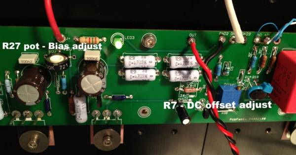
Bias is controlled by R27. (This pot actually sets the AC gain of the Aleph Constant Current Source, but it also has a direct effect on bias.) Offset is controlled by R7.
DC offset is very easy - connect your meter, reading DC volts, across the output jacks and adjust R7 until it reads zero.
The most important suggestion is to set R27 to approx. 68K when you install the pot on the PCB, long before you get to this step.
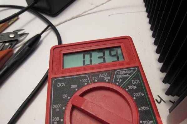
Power up the amp, measure the voltage drop across one of the source resistors on the right side of the PCB. These are the output transistors.
Set R27 so you read approx. 0.35V across this resistor.
Let the amp sit and warm up for 1/2 hour.
Once warm, re-adjust R27 so you read 0.4V (400mV) drop across the resistor.
Now zero the DC offset with R7.
Check to see that the bias didn't change much with the change in offset, re-adjust one more time if necessary.
Place the lid on the amp and let it sit for another 1/2 hour. Check the bias one last time and see if there was any drift with everything to operating temp. The rule of thumb for maximum temperature is 65C on the devices, 55C on the heatsinks.
That's all!
……………………………………….
Now for a few measurements -
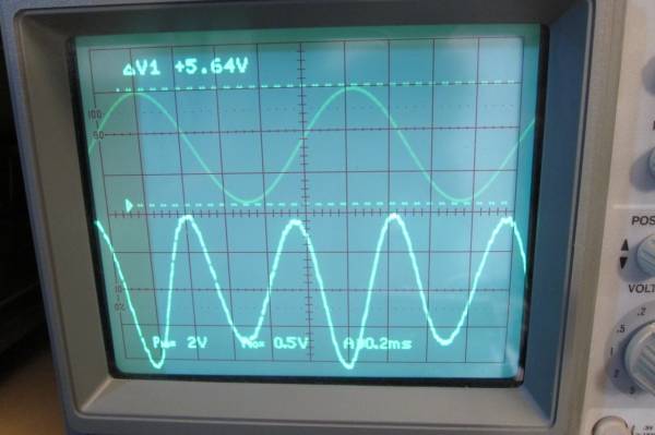
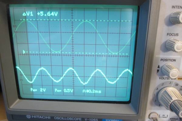
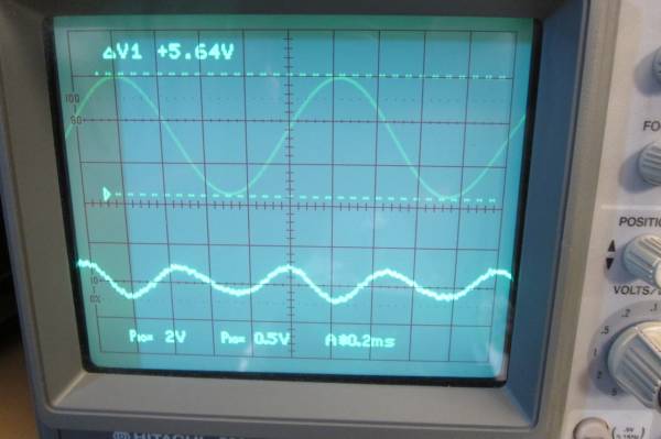
I recorded a few datapoints while giving the amp a 1000Hz sinewave of sufficient voltage to drive 1W into a 4 ohm load resistor.
5.64V pk-pk = 1.993V RMS
1.993Vrms^2 = 3.97 / 4ohm = .99W Close enough.
The top trace is the fundamental signal given to the amp. The bottom is the distortion residual waveform. The scale of the distortion analyzer and the oscilloscope is not changed in any photo.
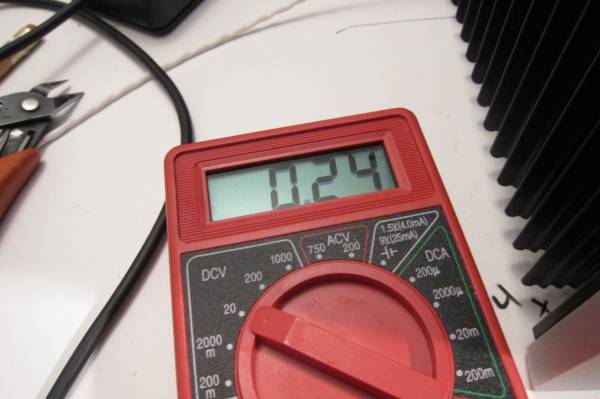
The first measurement is at 0.24V bias. This is .5A or 11W with the 21.2V rails (under load) in my amp.
Why this number? Simple, it's about the minimum bias where the amp seems to behave properly. Lower amounts than this and weird things start to happen as the CCS isn't doing it's job…
This amount of bias sounds fine.
The important thing is to look at the general shape (well behaved, no hiccups, or strange bumps, looks mostly like a sinewave) and size of the distortion residual. (Bottom trace)
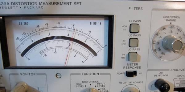
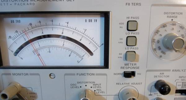
And here is the measurement. The meter is set to the 0.3 scale, look at the arc below the mirror and read 0.21%
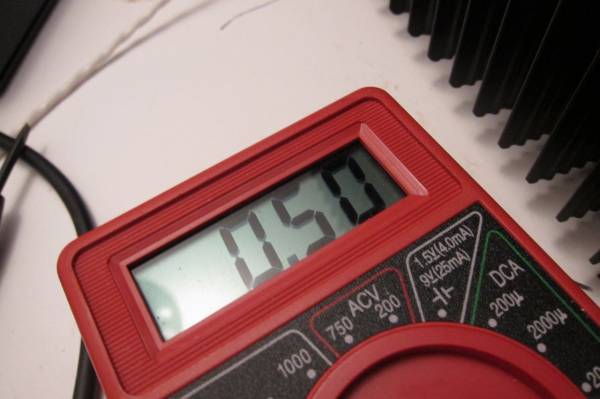
Now to increase the bias to the recommended amount, 400mV (I had it just on the edge and the meter read .39 when I took the photo….) 400mV bias = .85A = 18W/device
You can see how the distortion residual is smaller, and of a slightly smoother shape.
The scale has not been changed and the distortion is now 0.07%
As this amp is built in a 5U chassis, I will crank the bias to the hottest I want to take it (where the Mosfets are just under 160F / 70C) This is slightly above the 65C recommended for good longevity. The heatsinks are about 130F/55C. I suspect that if I were to use the Keratherm red silpads or thin mica&grease I would have slightly cooler devices and warmer sinks. 500mV bias = 1.06A = 22.55W/device. This is hot. You could not do this if you build your amp in the 4U chassis without a fan somewhere.
Again, the residual is smaller, and flattening out a bit. (Zero distortion would be completely flat.)
http://www.diyaudio.com/forums/redi...AJ500mvBiasDA.jpg.pagespeed.ic.9TxW2CqEMI.jpg
So what does making things really hot gain you in THD? The new number is 0.045% This proves that you can decrease distortion a little by increasing the bias, assuming you can keep things cool.
I want to know what instrument is measuring your distortion? A bit like an oscilloscope. Can you tell me the model number?
There are two instruments here: A distortion analyzer (looks like an HP339a)
and an oscilloscope to display the output waveform and the distortion residual.
The residual waveform is an output of the analyzer.
and an oscilloscope to display the output waveform and the distortion residual.
The residual waveform is an output of the analyzer.
There are two instruments here: A distortion analyzer (looks like an HP339a)
and an oscilloscope to display the output waveform and the distortion residual.
The residual waveform is an output of the analyzer.
Thank you for your answer.
I also saw similarities in the Douglas Self amp design manual to analyze distortion, but the two waveforms are not very similar. Is their principle the same?
The residual distortion of the Aleph is very well behaved, it won't be as ugly and jagged as the residual from a ClassAB push-pull amp.
Yes, the principal and measurement is identical to what D. Self talks about.
Yes, the principal and measurement is identical to what D. Self talks about.
@Mazeppa
Is there continuity between pins on Q7? From the photos it looks like there's something connecting two of the pins.
Is there continuity between pins on Q7? From the photos it looks like there's something connecting two of the pins.
The residual distortion of the Aleph is very well behaved, it won't be as ugly and jagged as the residual from a ClassAB push-pull amp.
Yes, the principal and measurement is identical to what D. Self talks about.
I want to know how this distortion residual waveform is formed? Is the input and output signals subtracted from the same amplitude? Because I can't find the same distortion meter in my place.
The fundamental (the test tone) is subtracted from the output with a very steep and very deep notch filter, the distortion is what is remains after that subtraction.
http://thehistoryofrecording.com/Test_Equipment/Manuals/HP/HP-339A_Manual.pdf
http://thehistoryofrecording.com/Test_Equipment/Manuals/HP/HP-339A_Manual.pdf
The fundamental (the test tone) is subtracted from the output with a very steep and very deep notch filter, the distortion is what is remains after that subtraction.
http://thehistoryofrecording.com/Test_Equipment/Manuals/HP/HP-339A_Manual.pdf
I understand, thank you very much! !
@Mazeppa
Is there continuity between pins on Q7? From the photos it looks like there's something connecting two of the pins.
Went back and checked, sure does look that way.
DVM between Q7 center and pin to right starts @ .810 Meg Ohm and begins counting down.
Tell me, is it okay to flood the board with denatured alcohol to get it good and clean after components have been installed?
As can be seen, my brush and wipe technique was only moderately successful.
Last edited:
- Home
- Amplifiers
- Pass Labs
- Aleph J illustrated build guide
