Hi Alan,
Your dc offset figure is excellent. Mine are never that good. 🙂
As for the output stage current, you can do that by measuring the voltage across the
0.47 ohm source resistors (which you've already done.) Your
measured 0.4V across the resistor sounds about right.
Cheers,
Dennis
Your dc offset figure is excellent. Mine are never that good. 🙂
As for the output stage current, you can do that by measuring the voltage across the
0.47 ohm source resistors (which you've already done.) Your
measured 0.4V across the resistor sounds about right.
Cheers,
Dennis
What a relief
Well, finally got my 1rst channel board done and installed.
I have the PS set up for 240VAC in.
Initital trial with 120VAc for approx 50% rails voltage.
Did a quick power up, all LED's came on, no smoke or funny smells.
Had a test driver and my iPhone hooked up, brought the volume up and
music came out! 😀
Couldn't resist listening for a couple of minutes, then rolled it back down.
I was as proud as only a newb amplifier assembler with limited electronics background could be.
Never would have tried it without the excellent build guide by 6L6 and surety of help from the forum.
Silent on power up, but there was a pop-pop on power down that was a little louder than I liked, though.
Next I'll rig for 240VAC and begin the initial adjustment procedure. Should have time tomorrow for that.
Hi Aljordan,
I built my J as per the BOM just as you did, but with a 400VA transformer. Your mention of the J being a little bright in the treble at first was exactly the same for me. Not that it sounded badly. It did smooth out after a couple of weeks listening to music daily. Maybe it’s a little more sensitive to break in?
To your note, I left the amp playing most of the day yesterday and today while I went off to work. Tonight while listening, it appears the amp has mellowed quite a bit compared to a couple of days ago. Maybe I didn't give it enough time over the past month, as I was mainly listening to the M2. Or maybe it sounds better after its been on for a while. Anyway, the treble sounds more tame and natural and quite a bit easier on the ears. It doesn't have the etched and dry quality that's been bothering me, if that description of treble makes any sense.
~~~~~~~~~~~~~~~~~~~
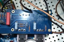
Aleph J chassis guide
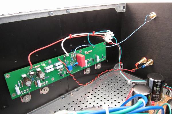
This photo shows (behind all the various wires, sorry…) the mounting of the heatsink brackets to the heatsinks themselves, the back and the bottom.
Posted by: 6L6
Original Content:
Was doing the ol' check-double check thing and the Input wiring caught my eye.
I'm using single ended inputs in my project.
I have the RCA jack center pin wired to +In, RCA jack tab wired to -In.
In the photo above, it appears that RCA jack center pin is wired to -In,
RCA jack tab wired to +In.
1. Am I cross eyed on this, or should I reverse my wiring?
2. -In to GND jumper is not just for aligning bias and DC offfset, but permanent, correct?
3. Input still need to be jumpered (+In to -In) temporarily for bias and DC offset alignment?
RCA center to +in
RCA tab to ground
Jumper -in to ground
Shorted inputs not required for setting offset
RCA tab to ground
Jumper -in to ground
Shorted inputs not required for setting offset
Uh-oh
Hit some trouble when I went to full voltage for the alignment procedure.
DVM across R18 read .850V. Adjusting R27 (set to 68K when installed) had no effect on this reading.
Rail voltages were +22.88 and -23.5 measured at the PCB.
Powered down, connected iPhone to input for music check as on initial 50% power up when I got music to the test driver but this time got only a loud pop-pop-pop from the driver then silence.
By this time I'm noticing heat building, checked temps just below mosfets on the heat sink with a non contact thermometer. Power had been on only a few minutes.
Q6 = 90.8F
Q5 = 98.2F
Q8 = 130.6F
Q7 = 136.4F
Powered down after I took those temp readings.
Input connections at the time were RCA center pin to +IN, RCA tab to -IN.
I pulled the PCB to reconnect input to the configuration of RCA center pin to +IN, RCA tab to GRND, jumper between GRND and -IN.
Awaiting advice from those that know more about such things than I before
proceeding.
Signed,
One of the NeedyBoyz
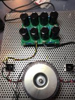
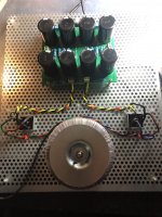
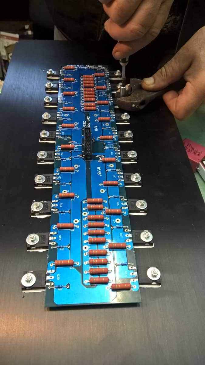
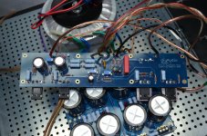
finished amplifier cards and psu. waiting for my chassis to come. so the assembly can begin 🙂
Attachments
Last edited:


Hit some trouble when I went to full voltage for the alignment procedure.
DVM across R18 read .850V. Adjusting R27 (set to 68K when installed) had no effect on this reading.
Rail voltages were +22.88 and -23.5 measured at the PCB.
Powered down, connected iPhone to input for music check as on initial 50% power up when I got music to the test driver but this time got only a loud pop-pop-pop from the driver then silence.
By this time I'm noticing heat building, checked temps just below mosfets on the heat sink with a non contact thermometer. Power had been on only a few minutes.
Q6 = 90.8F
Q5 = 98.2F
Q8 = 130.6F
Q7 = 136.4F
Powered down after I took those temp readings.
Input connections at the time were RCA center pin to +IN, RCA tab to -IN.
I pulled the PCB to reconnect input to the configuration of RCA center pin to +IN, RCA tab to GRND, jumper between GRND and -IN.
Awaiting advice from those that know more about such things than I before
proceeding.
Signed,
One of the NeedyBoyz
Send some clear, well lit pictures of the amp boards.
@Mazzepa
inputs shorted , no load on output
one DMM set to 2Vdc across (any) mosfet source resistor
second DMM set to 2Vdc across speaker terminals
working on one channel at time , second channel (somehow) disconnected from PSU
report here what readings are
inputs shorted , no load on output
one DMM set to 2Vdc across (any) mosfet source resistor
second DMM set to 2Vdc across speaker terminals
working on one channel at time , second channel (somehow) disconnected from PSU
report here what readings are
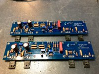
Have not started the 2nd board.
Hope these photos are good enough for analysis.
EDIT: Would someone please identify which are source resistors by schematic number, please?
Hope these photos are good enough for analysis.
EDIT: Would someone please identify which are source resistors by schematic number, please?
Attachments


Last edited:
3W ones , connected to mosfet sources
though , do not power poor thing without mosfets heatsinked (properly)
though , do not power poor thing without mosfets heatsinked (properly)


What component is used for the currentlimiter resistor for the led?Hope these photos are good enough for analysis
What component is used for the currentlimiter resistor for the led?
2 12V LED's in series.
Twitchie,
Q2-ZTX550 and Q3,4-ZTX450. I looked up the datasheets to ensure correct polarity and think I've got them correct. Certainly possible I'm wrong, will check that yet again.
Last edited:
Input shorted, powered up. Rails both @ 22.8V
Across R18 = .940V
Speaker Terminals = 15.9V initially, slowly to 16.4 then power down.
Now that's what I call some DC offset.
Checked test driver voice coil, it survived.
Rechecked Q2,3,4 again. I'm as sure as I can be that they are in the correct positions and polarity.
Across R18 = .940V
Speaker Terminals = 15.9V initially, slowly to 16.4 then power down.
Now that's what I call some DC offset.
Checked test driver voice coil, it survived.
Rechecked Q2,3,4 again. I'm as sure as I can be that they are in the correct positions and polarity.
When I first fired up my Aleph-J, I had the BJTs in backwards and I saw full rail voltages across the outputs but you've double checked this already.
Where did you source the jfets from (Q1A/Q1B)?
Where did you source the jfets from (Q1A/Q1B)?
- Home
- Amplifiers
- Pass Labs
- Aleph J illustrated build guide