Well I’ve powered up my first Aleph J build. I’m am a bit nervous about the final setup as it’s new territory for me so please excuse my obvious insecurity with these questions.
I’m assuming DC offset is done with the power off, am I correct?
I am getting .1 volt measurement at the output terminals and cannot seem to go lower when adjusting R7 for offset. Does this indicate a problem?
From reading here it seems the lower the bias set the lower wattage the amp puts out and the cooler it runs, would it ok to bias to .30V (or some voltage less than the target .40V) and still have a great sounding Aleph J ?
While powered up I get a reading of 17.44V at the speaker terminals is this in line with expectations?
Thermistors are hot to the touch, is this normal?
Why is R8 a variable resistor and what does it adjust?
Thank you in advance for the help! You guys are the greatest!
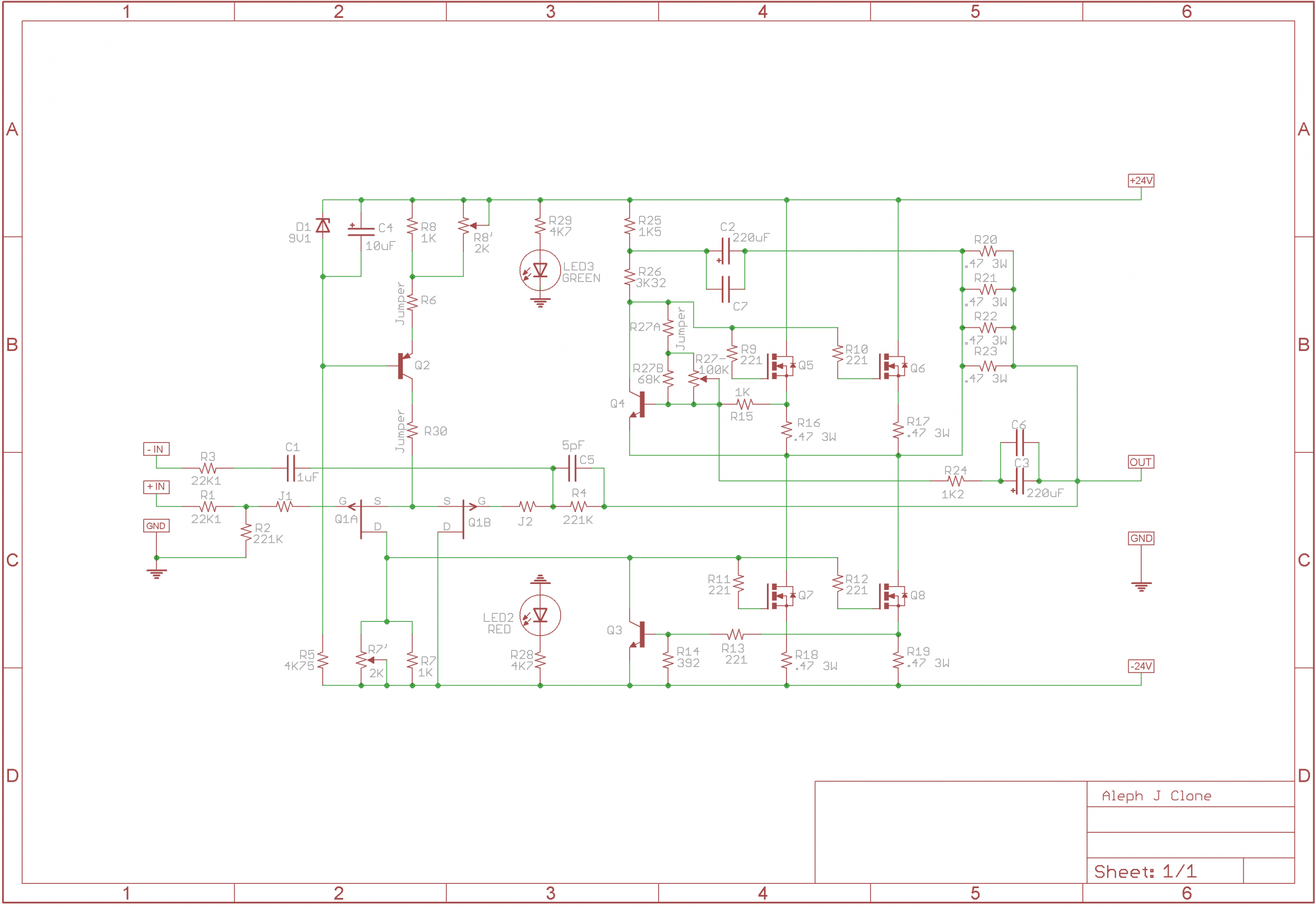
referenced to attached schematic
both inputs shorted to GND , output no load
put 10 or 100R or 1K in R30 position
put one voltmeter across R19
power on , check voltage across R30 and set with R8 to have 10mAxR19 value ; example : 10mA x 1K =10Vdc
you've done with R8 for good
relocate that voltmeter between output + and output
observe voltage across R19 , correct halfstep to intended value with R27
observe voltage on output , correct slowly with R7 to 0V
close the lid , let it warm
repeat corrections with R27 and R7 (they're dependent) as amplifier warms up , finishing in temp. equilibrium
remember that amplifier is in temp. equilibrium only if having top lid in place
.......
relocate that voltmeter between output + and output -..........
referenced to attached schematic
both inputs shorted to GND , output no load
put 10 or 100R or 1K in R30 position
put one voltmeter across R19
power on , check voltage across R30 and set with R8 to have 10mAxR19 value ; example : 10mA x 1K =10Vdc
you've done with R8 for good
relocate that voltmeter between output + and output
observe voltage across R19 , correct halfstep to intended value with R27
observe voltage on output , correct slowly with R7 to 0V
close the lid , let it warm
repeat corrections with R27 and R7 (they're dependent) as amplifier warms up , finishing in temp. equilibrium
remember that amplifier is in temp. equilibrium only if having top lid in place
“both inputs shorted to GND”
Does this mean rca cables plugged in but not to anything on the other end?
Well I’ve powered up my first Aleph J build. I’m am a bit nervous about the final setup as it’s new territory for me so please excuse my obvious insecurity with these questions.
I’m assuming DC offset is done with the power off, am I correct?
I am getting .1 volt measurement at the output terminals and cannot seem to go lower when adjusting R7 for offset. Does this indicate a problem?
From reading here it seems the lower the bias set the lower wattage the amp puts out and the cooler it runs, would it ok to bias to .30V (or some voltage less than the target .40V) and still have a great sounding Aleph J ?
While powered up I get a reading of 17.44V at the speaker terminals is this in line with expectations?
Thermistors are hot to the touch, is this normal?
Why is R8 a variable resistor and what does it adjust?
Thank you in advance for the help! You guys are the greatest!
No. You can not set offset with amp off....must be on
Russellc
“both inputs shorted to GND”
Does this mean rca cables plugged in but not to anything on the other end?
working on one channel at a time ...... that's assuming
both inputs means - both negative an positive input legs
so , take one XLR jack , short all 3 pins together , plug it in
working on one channel at a time ...... that's assuming
both inputs means - both negative an positive input legs
so , take one XLR jack , short all 3 pins together , plug it in
Ah, gotcha. Thanks!
working on one channel at a time ...... that's assuming
both inputs means - both negative an positive input legs
so , take one XLR jack , short all 3 pins together , plug it in
This isn't my amp but like the attached?
Attachments
![dsc01595[1].jpg](/community/data/attachments/604/604139-2354b59e602ae1c118a4c2c41831bb4a.jpg?hash=I1S1nmAq4c)
Count to three. No more. No less. Three shalt be the number thou shalt count, and the number of the counting shall be three. Four shalt thou not count, nor either count thou two, excepting that thou then proceed to three. Five is right out.
I've finally read all the the forum pages on the Aleph J and am ordering parts but have some questions about the Capacitors.
From my understanding, the caps in the PSU are not very critical. I'm looking at these mostly because of the 3000 hour life .
381LX223M035A052 Cornell Dubilier - CDE | Mouser
I've seen some replacement of C1, C6 and C7 with different caps than are on the BOM, usually with Mundorf. Does anyone highly recommend changing these caps from the start? Has someone noticed an improvement with the different caps?
Count to three. No more. No less. Three shalt be the number thou shalt count, and the number of the counting shall be three. Four shalt thou not count, nor either count thou two, excepting that thou then proceed to three. Five is right out.
Yes I can count. Just asking if you can use pins to connect all 3 like shown or wrap some wire around 3 male pins?
Not critical....I guess that depends on your idea of critical. I scan over the caps specs, and usually end up with something with far more hours, and 105 degree specs. Remember, you are listening to the power supply, basically being modulated by the amp.....but what the heck do I know. I am famous for destroying anvil with rubber hammer.
Russellc
Russellc
Thank you, Prodanovic and thank you, Russell! Seems I missed a pretty big chunk of information when reading this build guide, my apologies I should have been more attentive. Once I have the chance to follow your guide lines I’ll come back with an update. Many thanks!
referenced to attached schematic
both inputs shorted to GND , output no load
put 10 or 100R or 1K in R30 position
put one voltmeter across R19
power on , check voltage across R30 and set with R8 to have 10mAxR19 value ; example : 10mA x 1K =10Vdc
you've done with R8 for good
relocate that voltmeter between output + and output
observe voltage across R19 , correct halfstep to intended value with R27
observe voltage on output , correct slowly with R7 to 0V
close the lid , let it warm
repeat corrections with R27 and R7 (they're dependent) as amplifier warms up , finishing in temp. equilibrium
remember that amplifier is in temp. equilibrium only if having top lid in place
Well I guess I’m just confused. I put a jumper in the R30 position per the first page of this thread. So to set offset and bias i need to disassemble, remove the jumper, then add 10 or 100R or 1K in R30 position ?
Some consider Nelson's amps to be magic..........I’m assuming DC offset is done with the power off, am I correct?

Well I guess I’m just confused. I put a jumper in the R30 position per the first page of this thread. So to set offset and bias i need to disassemble, remove the jumper, then add 10 or 100R or 1K in R30 position ?
I prefer being able to set current through input JFets , so - yes
Scottjoplin I apologize for my ignorance. When reading Jim’s post #3 it is not clear to me (even re reading now) that power is on while setting DC offset as it is not indicated to turn power on until after he discusses setting DC offset. I appreciate your input all the same.
ZenMod once I have:
“both inputs shorted to GND , output no load
put 10 or 100R or 1K in R30 position
put one voltmeter across R19
power on , check voltage across R30 and set with R8 to have 10mAxR19 value ; example : 10mA x 1K =10Vdc
you've done with R8 for good” does the resistor you have me place in R30 stay or once R8 is set should the resistor be removed and the jumper put back as 6l6 has it?
To set offset and bias the way dear ZenMod has described I will have to disassemble my build so this is going to take a long while. It seemed so simple when reading post #3 but I’m just a newb and simply don’t have the experience or knowledge yet to have known what I was getting into I guess.

Yes I can count. Just asking if you can use pins to connect all 3 like shown or wrap some wire around 3 male pins?
you can use whatever you want ......solder them inside in box between pins ,use aligator clip cables, XLR jack without cable but shorted pins with tiny wires........
be creative ......... and be sure that contact between tgese 3 pins is not intermittent ........ or you'll have glitches
you can use whatever you want ......solder them inside in box between pins ,use aligator clip cables, XLR jack without cable but shorted pins with tiny wires........
be creative ......... and be sure that contact between tgese 3 pins is not intermittent ........ or you'll have glitches
Gotcha, thanks for the clear response, its greatly appreciated
- Home
- Amplifiers
- Pass Labs
- Aleph J illustrated build guide