Buzzford,
Thanks for the feedback.
Henry,
I think your BOM is missing C7.
I have an assortment of female/female standoffs, the kind I prefer. In this case I bought a few of the 5mm male/female type to use the pre-drilled and tapped holes in the heat sink. I have already added taller ones to my Mouser project manager, to include in my next order.
Zen Mod,
I am using a case purchased from the DIYAudio store. The heat sink already has the holes pre-drilled and tapped so changing the point where the legs are bent would require more drilling and tapping. I did prop the standoffs up using washers, and it was an easy fix. However, since I had used the same exact standoffs for the F5 boards with no problems, I wanted to determine what caused the PCBs to touch the MOSFETs. Since these boards are meant to prototype the design, trimming the edge is something easy to do.
Can you trim offsetlower?Buzzford,
Thanks for the feedback.
Henry,
I think your BOM is missing C7.
I have an assortment of female/female standoffs, the kind I prefer. In this case I bought a few of the 5mm male/female type to use the pre-drilled and tapped holes in the heat sink. I have already added taller ones to my Mouser project manager, to include in my next order.
Zen Mod,
I am using a case purchased from the DIYAudio store. The heat sink already has the holes pre-drilled and tapped so changing the point where the legs are bent would require more drilling and tapping. I did prop the standoffs up using washers, and it was an easy fix. However, since I had used the same exact standoffs for the F5 boards with no problems, I wanted to determine what caused the PCBs to touch the MOSFETs. Since these boards are meant to prototype the design, trimming the edge is something easy to do.
Can you trim offsetlower?
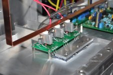
I did not install any trimpot on the board, wanted to try a standard build first. The picture was taken about 20 minutes after setting the rails at +23V/-23V and the DC offset was still going down but slowly. I was hoping the trimpots would not be necessary since I got tightly matched JFETs and MOSFETs.
I did not install any trimpot on the board, wanted to try a standard build first. The picture was taken about 20 minutes after setting the rails at +23V/-23V and the DC offset was still going down but slowly. I was hoping the trimpots would not be necessary since I got tightly matched JFETs and MOSFETs.
Standard build would have trimpot on leg of LTP to set bias of lower get as well as adjust offset.
Standard build would have trimpot on leg of LTP to set bias of lower get as well as adjust offset.
I did not see them in Nelson's schematic. Did I miss a later update?
You are correct, in that it is unnecessary if you have perfectly matched fets, but as your build shows, even perfectly matched fets yield non perfect results. Something as simple as poor MOSFET mounting could result in mode offset. Your number is not at all unacceptable, but with pot, 0-5mV offset is achievable. It really comes down to flexibility, which will be necessary in most builds. If after adjusting, you want just resistor, it can be done and is a good suggestion.
I'll install the trimpots then. This is what I am thinking:
R7 - Replace 1K resistor with 2K trimpot
R8 - Replace 1K resistor with 2K trimpot
R27 - Replace 68K1 resistor with 51K1 resistor + 20K trimpot
R7 - Replace 1K resistor with 2K trimpot
R8 - Replace 1K resistor with 2K trimpot
R27 - Replace 68K1 resistor with 51K1 resistor + 20K trimpot
I'll install the trimpots then. This is what I am thinking:
R7 - Replace 1K resistor with 2K trimpot
R8 - Replace 1K resistor with 2K trimpot
R27 - Replace 68K1 resistor with 51K1 resistor + 20K trimpot
r7 is more than likely all that will be needed and it, only for a while.
Since there are less available trimpot values than resistor values, would the 56K2 + 20K combination be adequate?
It should be ok. I have a little bit bigger sinks, so I bias my Aleph a bit higher and have 100k pot instead of 56k resistor in schematics.
r7 is more than likely all that will be needed and it, only for a while.
I'll try that on the other channel since it isn't mounted on the heat sink yet. But it may have to wait until the weekend as I have very little free time during the week.
please - make difference between using perfectly matched and perfectly graded (and matched) parts ;
who sez that Pa is putting always exactly same resistor values ?
who sez that Pa is putting always exactly same resistor values ?
🙂please - make difference between using perfectly matched and perfectly graded (and matched) parts ;
who sez that Pa is putting always exactly same resistor values ?
please - make difference between using perfectly matched and perfectly graded (and matched) parts ;
who sez that Pa is putting always exactly same resistor values ?
Can you tell me the difference between "tightly" and "perfectly"?
😉
JFETs are graded by IDSS and grouped in 3 ranges identified as Green, Blue and Violet. For the 2SJ74 they are GR: 2.6~6.5 mA, BL: 6.0~12 mA, V: 10~20 mA
Using JFETs from the same manufacturing lot and same IDSS grade, with the help of one of the meters in the photo and an HP power supply, I measured IDSS on the self-biased devices at 10V. The output of the power supply, after about 45 minutes, is stable to the fifth digit. I always wait at least 1 hour before starting. In the channel on the photo the JFETs have IDSS 9.31mV and 9.36mV. In my view, "tightly" matched.
MOSFETS I matched for similar Vgs. They also come from the same manufacturing lot as that increases the chances of other parameters being also similar, and each pair is "tightly" matched to within 10mV. I am not familiar with grading for those.
As for adjustments in production I am fully aware of them. I even remember seeing piggybacked resistors in a photo of a First Watt amplifier and Nelson explained what it was.
I made a commitment to build the boards quickly and had the parts in hand for a "standard" build, as the boards I intended to use do not have room for trimpots. I made good on my commitment to 6L6. Now, with the help of Mighty ZM and other members, I'll try to make the amplifier as close to "perfect" as possible.
🙂
Feel free to add, as much as you want, to my little knowledge at any time. I am here to learn and have fun!
Last edited:
Taking it further would mean matching for Yfs, Ciss, and leakage. He was simply trying to reiterate the practical use of pot at R7.
point wasn't in tightly or perfectly , but in difference between matched and graded
you can make an amp without any pot if you have parts stashed in small drawers , each of them having label by grade
then all you need is coffee , cigarette and calculator , to be able to choose from which drawer you are going to pick next part
so - be clever - put pots where they need to be , set amp after temp equilibrium , then pull pots out and replace with fixed resistors
even if my cleverness ends right after setting da amp ; I don't mind having good cermet here and there , as long I'm understanding role of the part
- Home
- Amplifiers
- Pass Labs
- Aleph J for Universal Mounting Spec