whatever you do - edit those default Eagle packages , to have bigger pads
especially for resistors , but for semis too
especially for resistors , but for semis too
Whatever you do - edit those default Eagle packages , to have bigger pads.
Especially for resistors , but for semis too
That seems like good advice!
whatever you do - edit those default Eagle packages , to have bigger pads
especially for resistors , but for semis too
Agreed. So I need some dimensions :
1. Resistors (small one) :
- Spacing = 10mm ( need longer?)
- Pad Diameter = ? mm
- Drill Diameter = ? mm
2. Cap C2, C3 :
- Spacing = 5.08 mm ( need bigger?)
- Pad Diameter = ? mm
- Drill Diameter = ? mm
3. Big Resistor :
- Spacing = 17mm ( need longer?)
- Pad Diameter = ? mm
- Drill Diameter = ? mm
4. Wire Pad
- Pad Diameter = ? mm
- Drill Diameter = ? mm
5. C1 elco or Film ?
6. Add Pot to R7 or R8 ?
7. Semi To92 (I use BC), and SJ74
- Pad Diameter = ? mm
- Drill Diameter = ? mm
8. IRFP Semi :
- Pad Diameter = ? mm
- Drill Diameter = ? mm
9. For Led wich one do you prefer, 2 Led (one Led for Each Rail ) or 1 Led as on schematic?
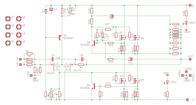
For Reference i use this schematic, but I change ZTX to BC.
Attachments
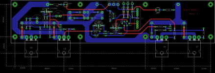
The intent of this board is that it will become the one sold in the DIYaudio store -- Hence the UMS and a few other tweaks.
Finally, an Aleph in the store? Cool!
My one request is that pads are spaced such that all the resistors will fit without having to stand them up or contort the leads (unlike the other Aleph board...).
My one request is that pads are spaced such that all the resistors will fit without having to stand them up or contort the leads (unlike the other Aleph board...).
LOL!!! I'm working on that right now... 🙂 🙂 🙂
5. C1 film as you have drawn it in most recent revision. 🙂 People will want to use film, and 1uf at these voltages is small.
6. R7 Yes. R8 ?If there is space for it...?
9. One LED each rail. Nelson said the LED as drawn in schematic was nothing more than panel lamp. With 2 they can be indicator for rails, or if people just want lamp, they can use one.
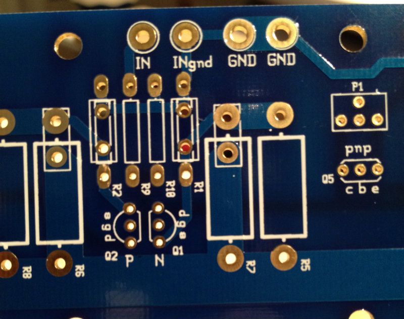
Pinout of BC transistors is CBE. Pinout of ZTX is EBC. How about leave silkscreen genderless, but mark the pinout and the channel of device. (see Q5 in photo) This is similar to current F5 F4 boards.
Also, measured from current F5 board - (And I can locate my fine rule, so I won't even guess the hole sizes)
Small resistor lead spacing 12.5mm (That will easily fit a Dale CMF60) and input resistors have 2nd set of 5mm holes for expensive Caddock or vishay square package (see photo)
Large resistor lead spacing 15mm with 2nd hole for 5mm bent knee lead square package (see photo)
6. R7 Yes. R8 ?If there is space for it...?
9. One LED each rail. Nelson said the LED as drawn in schematic was nothing more than panel lamp. With 2 they can be indicator for rails, or if people just want lamp, they can use one.
Pinout of BC transistors is CBE. Pinout of ZTX is EBC. How about leave silkscreen genderless, but mark the pinout and the channel of device. (see Q5 in photo) This is similar to current F5 F4 boards.
Also, measured from current F5 board - (And I can locate my fine rule, so I won't even guess the hole sizes)
Small resistor lead spacing 12.5mm (That will easily fit a Dale CMF60) and input resistors have 2nd set of 5mm holes for expensive Caddock or vishay square package (see photo)
Large resistor lead spacing 15mm with 2nd hole for 5mm bent knee lead square package (see photo)
Last edited:
Still on progress change eagle lib :
1. Small R spacing 12mm, drill dia 1mm ?, add 5 mm spacing for R Input.
3. Big R spacing 15 mm are enough?, add 5mm R
7. Add Pinout, change silk
For drill dia : small component 1mm, Big R 1.5mm, wire 2mm ?
Didiet
1. Small R spacing 12mm, drill dia 1mm ?, add 5 mm spacing for R Input.
3. Big R spacing 15 mm are enough?, add 5mm R
7. Add Pinout, change silk
For drill dia : small component 1mm, Big R 1.5mm, wire 2mm ?
Didiet
Trim pots on:
R7 -trims output DC offset to zero
R8 -sets front-end LTP total bias current
R24 -adjusts Aleph Current Source to taste
R27 -trims 0.6V reference across R16/R17 to set output stage bias current
From way back when, done in AutoCAD... http://www.diyaudio.com/forums/pass-labs/48303-hotrod-aleph-circuit-board-13.html#post717642
Didiet - I am waiting to get some specific answers regarding the potentiometers. Sory for the lack of communication.
Everything is looking very good so far! 😀 😀 😀 😀 😀
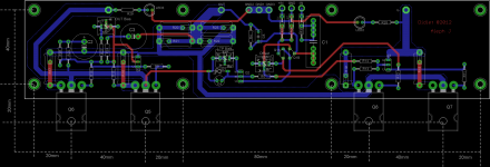
Once the boards are tweaked and look good I am planning on getting a pair made locally for proof of concept and prototype.
Everything is looking very good so far! 😀 😀 😀 😀 😀
Once the boards are tweaked and look good I am planning on getting a pair made locally for proof of concept and prototype.
That looks great!
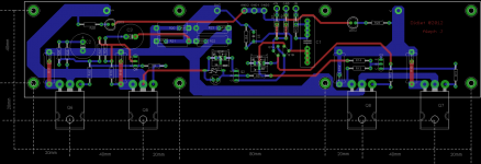
Could you rotate the pot 90 deg and add the pads for the resistor, similar to the other pots?
Could you rotate the pot 90 deg and add the pads for the resistor, similar to the other pots?
Yes, thank you! That is great. 🙂 🙂 🙂
A question -- I do not have much resolution when looking at the drawing, so I need to ask, ?Are the potentiometers being connected as variable resistors? I.E., with the wiper connected to one of the legs?
A question -- I do not have much resolution when looking at the drawing, so I need to ask, ?Are the potentiometers being connected as variable resistors? I.E., with the wiper connected to one of the legs?
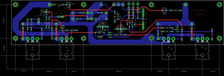
nice board and good distance between the IRFP's. Would be nice to have pads to bridge to RCA. When will the board be available?
All a nice holiday season
All a nice holiday season
nice board and good distance between the IRFP's. Would be nice to have pads to bridge to RCA. When will the board be available?
All a nice holiday season
bridge to RCA is just solder in a jumper. there is realy no need for extra pads for it🙂
- Home
- Amplifiers
- Pass Labs
- Aleph J for Universal Mounting Spec