Thanks Wowbagger! Just learned something new.
PPinto1 - disregard my previous post. My fault for not looking. I didn't see the correct code on the parts. 😀 It makes it much easier to help if for future builds you put the number with the resistance facing upward. Not your fault I read it too quickly, but it'll help in the future for things like this.
Eddyvb - still, great eyes and call out.
Wowbagger - yep. I saw R9 and R10 looked good in the pic you linked, but I jumped to the wrong conclusion (read the code incorrectly) for R11 and R12. I got all excited when Eddyvb posted. I had been staring at the pics for 20 mins going cross-eyed. 😀
Ppinto - just peek at R9 and R10 to be sure they're 220R.
Ppinto - just peek at R9 and R10 to be sure they're 220R.
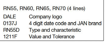
Still strange, the J code dale resistors are 3 digits. Here are 4 digits. So is it 19K, but what with the fourth digit?
Still strange, the J code dale resistors are 3 digits. Here are 4 digits. So is it 19K, but what with the fourth digit?
See above edited post
PPinto1 - I've checked what I could see. I'll assume the earlier miswiring and subsequent checks burned the MOSFETs and that replacing them, doing some short checks, a dim bulb check, and powering up in a controlled sequence will result in success. 😀
It'd be great if it were something obvious and visible. The solder work on the existing FETs needs some love, but you can tidy that upon replacement.
Wowbagger - thanks again - I never knew the meaning of those codes. Still, I know better than to look for anything but the "4th" line on a Dale for the value. Mea Culpa.
it seems Newark is blocking Sissies from States
Jim linked "DS017 - Desoldering Pump, Deluxe SOLDAPULLT®, Heavy Duty, PTFE Nozzle, 330mm"
yeah, time for changing mosfets
considering bravery of OP, if things go rough, just cut mosfet legs ditto to pcb , you'll manage easier having free separate pins in holes
Thanks, I had a crappy one with rubber bulb, never could get it to work
right, I will try this one. I have taken to cleaning with solder wick and clearing hole.
Russellc
And remember, when using a solder sucker, keep the soldering iron on the joint! The sucker’s tip is Teflon for a reason. 🙂
Thanks for taking a look, everyone!
R9, R10, R11, & R12 all have 2210F printed on the. Sorry for the orientation.
I pulled R7 and R27 (pot) just to make sure they're working correctly. They are.
There are no shorts between the pins of the MOSFETs. If something is blowing them, I'd hate to burn up a set of good MOSFETs. Thanks for your very generous offer, ItsInYourHead; but I think I'll order another set for now.
Zen Mod: I've purchased all my MOSFETs from Newark, because they were out of stock everywhere. When you say that have to be matched "one pair up, second pair down", what does that mean? Will not doing so cause them to fail? Did I just get lucky on the working channel?
Would bad JFETs be able to make the MOSFETs fail?
@ppinto1: Within each group of two mosfets (for example, Q5/Q6) the parts
should be matched so that they share roughly the same current load.
(We are trying to get about 1.7A through the pair Q5 and Q6 and by matching
we want each of Q5 and Q6 to run at about 0.85A.)
With 'random' parts, you may find that one mosfet may be on while the other
one is off.
should be matched so that they share roughly the same current load.
(We are trying to get about 1.7A through the pair Q5 and Q6 and by matching
we want each of Q5 and Q6 to run at about 0.85A.)
With 'random' parts, you may find that one mosfet may be on while the other
one is off.
Dennis Hui: Oh! I figured they had manufacturing tolerances which would prevent a situation like that. I thought matching was suggested for audio quality purposes. It sounds like I could have working but unmatched parts?
You want to match when running the parts in parallel. In your case,
the numbers you measured in post #141 actually look reasonable. Were
those parts from Newark?
If they had come from the same tube package they may match fairly
well. The use of source resistors (R16-R18) also helps.
The general suggestion is to use matched parts. You can order more (say a
single full tube and measure and select) or get them pre-matched from a trusted
source.
I suggest you take up ItsAllInMyHead's kind offer. 🙂
Only so many people can tell you you're a duck before you need to start quacking... It sounds like I should take ItsAllInMyHead up on his kind offer.
I want to understand something first, though. Can the failure of any other component on the board cause the MOSFETs to fail?
I want to understand something first, though. Can the failure of any other component on the board cause the MOSFETs to fail?
oh yes, but from my own experience, age and stupidity are two most common reasons for malfunction
illustration - as I'm older , level of stupidity is sorta showing decrease tendency, but only because I'm slower than before

illustration - as I'm older , level of stupidity is sorta showing decrease tendency, but only because I'm slower than before
I bought a tube of 25 x MOSFETs from RS, which is Newark in the US. They all matched together straight out of the tube.
I just bought 25 and will match them. My rationale is that I have an upcoming build of an F6 (whenever I can source the input transformers), and I'm not sure the working side of this amp is properly matched. Furthermore, at the rate I'm burning them, I feel more comfortable having spares.
The schematic NP posts for testing uses a 15v power source. Does anyone know this can be 9V? If not, I'll scavenge my parts bin and see what I come up with.
Thanks, so much, ItsAllInMyHead, for your offer! This just makes more sense based on what's coming. Maybe I can pay it forward once my amps are sorted out!
- Home
- Amplifiers
- Pass Labs
- Aleph J - First Test Issues / No Sound / Blinking LEDs