Thanks ZM. When I try this, it blows a thermal breaker in the PS. I think I need to find another power option.
Update: I opened the cable of that laptop PS to find 3 wires, and two of them supply 19.4V. Retesting!
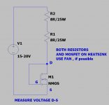
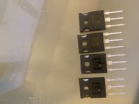
I have results. Using a 19.4v power source and a 50R resistor:
4.26v
4.26v
4.24v
4.18v
They would get warm when tested, but definitely not too hot to hold. I tested each for 30 - 32 seconds.
I don't understand how this gels with my previously finding a short between leads on one of them. I re-tested and don't see that now.
What do the measurements tell us?
4.26v
4.26v
4.24v
4.18v
They would get warm when tested, but definitely not too hot to hold. I tested each for 30 - 32 seconds.
I don't understand how this gels with my previously finding a short between leads on one of them. I re-tested and don't see that now.
What do the measurements tell us?
Last edited:
you're good, more than
put both 4V26 down , rest of them up (in Aleph CCS)
how you got bogus measurements before - who knows, I'm always blaming Gremlins, not my own stupidity

P.S. take care to use some isolators between mosfets and heatsink, and to check it with Ohmmeter, before powering up amplifier
🙂
put both 4V26 down , rest of them up (in Aleph CCS)
how you got bogus measurements before - who knows, I'm always blaming Gremlins, not my own stupidity
P.S. take care to use some isolators between mosfets and heatsink, and to check it with Ohmmeter, before powering up amplifier
🙂
To be clear, those are the first set that I removed. I'm still waiting for the replacements. When you say to check with the ohmmeter, can you explain the test? Was it in a previous post? Sorry to ask (if it's again), but I want everything to be perfect.
I meant - check is there proper isolation ( no puncture , so no connection) between mosfet drains and heatsink, after you mount (supposedly) new ones back on pcb and heatsink
if those you just tested are removed ones from pcb, then they're good and pretty well matched!
put them back, and mount everything on heatsink
in fact , please feel free to make a pause of few days and just stare at pcb, trying to find anything which isn't by schematic
considering all info you gave us , now I'm sorta confused ..... it was a short, there is no short, now mosfets are fine .........
The fact that R7 was actually malfunctioning is confusing too - was it bad when it was installed, or did something melt it?
😕
😕
I didn’t test R7 before installing, so. I’m not sure.
The MOSFETs have me confused, too. I reported what I saw. I’ll check them again. I can’t re-install them, though, because I cut their leads to remove them.
The order from Newark should come today. I’ll match 4 and test.
I think the correct components are installed because I was able to play music through it for a half hour after properly setting bias and offset. I re-assembled and never got it working again.
I’m not one to ignore a suggestion, though. Is there a place I can obtain a quality image of an empty board? It would help me identify component location, as the labels are mostly blocked.
Not the best quality, but it should work.

I also use the pics from the store on occasion for the same reason.
I also use the pics from the store on occasion for the same reason.
Thanks!
I'm looking forward to finishing up work today. I want to nail this.
I rechecked the MOSFETs for shorts, and I couldn't find any. I don't know what happened. My fear is that I'll pull the current MOSFETs and they'll test okay, too.
I'm looking forward to finishing up work today. I want to nail this.
I rechecked the MOSFETs for shorts, and I couldn't find any. I don't know what happened. My fear is that I'll pull the current MOSFETs and they'll test okay, too.
All joking aside - it's saved my bacon a number of times.
I'd seriously consider doing one just like this:
F6 Illustrated Build Guide
Since you want to do the F6 too. See the last section of 6L6's first post.
I'd seriously consider doing one just like this:
F6 Illustrated Build Guide
Since you want to do the F6 too. See the last section of 6L6's first post.
Something unexpected happened this morning. I had MOSFETs back-ordered with Mouser from my original order for the F6. They arrived. Test results:
4.15
4.14
4.14
4.14
Guess who's plugging in their soldering iron!
Don't feel bad about that, I cannabalized my entire F6 to make my Aleph J and never looked back. Don't misunderstand, F6 is a great amp, they ALL are. But having several it was by comparison more in the F5 camp, or leaning that way in tonal balance. The newer F5 has P3, and there are threads here about bringing out more H2 in F6, but I prefer the M2, BA3, and now Aleph J and the warmer sound. I dont miss F6 at all, and AlephJ is one of my all time favorites.
I still have the F6 boards, and will again work with them concerning various notes that others have posted since I built mine as well as Semisouth outputs. That will be a while, long list in front.
You will love Aleph J, it WILL be worth going through all this over.
Russellc
Thanks for the encouragement, Russellc. I'm going to need it. The behavior hasn't changed. I'm ready to pull everything out of the board and start over.
Thanks for the encouragement, Russellc. I'm going to need it. The behavior hasn't changed. I'm ready to pull everything out of the board and start over.
Well even that, new boards and all if necessary, this one is worth it. all ways refreshing to come back to after it's being out of rotation. Very special, delightful amp to listen to.
Russellc
Good things are coming out of this: I learned how to match JFETs and MOSFETs. This is my first experience with a kit from diyaudio store; and I think they're of great quality.
Most importantly, I feel a sense of community on this forum. I've been a member for 7 years (since I built a Tubelab SE), but this is the first time I've participated a lot.
When I pull resistors off the board, I'm going to measure every one to see if I made a mistake. I'm not sure how to check capacitors; but I'm sure they were installed with the correct polarity. I'll post what I find if anyone's interested.
Oh, by the way, I checked for continuity with each of the MOSFET pins and the chassis before powering up. To validate this test method, I tested for continuity between the chassis and hold-down screws - and found it. There was none for the MOSFET pins.
I'd love to figure out what I did wrong.
- Home
- Amplifiers
- Pass Labs
- Aleph J - First Test Issues / No Sound / Blinking LEDs