The other method is based on trying to wrap my head around an old papa post, tinkering on the bench, finally understanding it and making it work, then documenting it step by step. One, so I could share it. Two, so I could do it again a year later once I forget. Three, to have something to point people to because inevitability I’ll forget the details and not be very helpful.
It’s the same as pulling up a post with ZM’s “how to set up F5 pots” that the flyboy copy and pasted. Write it and keep going back to it.
It’s the same as pulling up a post with ZM’s “how to set up F5 pots” that the flyboy copy and pasted. Write it and keep going back to it.

Alex...I think one of these day...I'll have to look in the mirror and I'll have to slap myself! Or if we should meet I authorize you to slap me!ZM is dumb
for me, that always was comparing voltages across lower group (mosfets in neg rail) vs. same in upper group (Aleph CCS Mosfets)
any other approach is either too complicated to my liking, or simply above my head
exact physical arrangement, how to make easiest varying of Aleph CCS modulation resistor, that's trivial
I prefer 1pin sockets for said resistor, ensuring that you always have equal value in both channels; trimpot is working against that
Hi...hi...hi...

Good news guys!
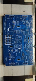
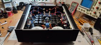
First ignition results and general adjustments/considerations.
1) to get 0.460mV on R25 I had to rotate P2 to the maximum (50K) so I got about 0.98A on Q10
instead on R29=0.53mV
also on
R24=0.53mV
R28=0.57mV
2) to get +/- 10mV offset (shorted input and no output load) I had to adjust P1 to about 170 Ohm
in this condition I obtain with 20°C TA max a heatsink temperature 55°C
3) I measured the voltage of 10V on R9 (therefore 10mA)
4) I measured 4.49V on Vce of Q7 (BC550)
In the afternoon I'll try to understand something about P3 regulation (AC gain) and I'll post measurements that will be done with an oscilloscope and Arta Software (I hope don't explode everything)
Attachments
Errata corrige voltage measurement SORRY!
R25=0.460mV was right !R29=0.453mV
R24=0.453mV
R28=0.457mV
Last edited:


Updates...
After several measurements I realized that in order to obtain the best compromise between THD and maximum available output power (with perfect shearing of the upper and lower part of the half-wave), the right compromise is R19 (AC gain resistor 1k ) with P3 removed and jumpered.
Scaled harmonic performance and good frequency response.
and that would be , numerically, what % of Aleph AC gain?
you know that (your) best compromise there is load-dependent ......
you know that (your) best compromise there is load-dependent ......
Hi Alex! Tomorrow i will finish the left channel, and in the afternoon i hope to listen It.
Stay tuned.
Stay tuned.
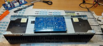
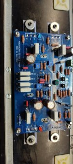
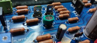
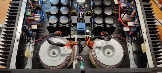
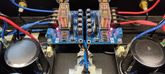
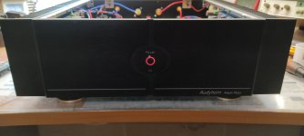
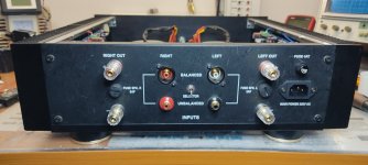
Finish....
Attachments
-
 IMG_20230506_103919.jpg256.4 KB · Views: 161
 -
 IMG_20230506_103338.jpg281.9 KB · Views: 157
 -
 IMG_20230506_103353.jpg407 KB · Views: 155
 -
 IMG_20230506_103406.jpg331.9 KB · Views: 150
 -
 IMG_20230506_103423.jpg330.4 KB · Views: 153
 -
 IMG_20230506_103433.jpg298.5 KB · Views: 160
 -
 IMG_20230506_103442.jpg349 KB · Views: 154
 -
 IMG_20230506_103454.jpg147.6 KB · Views: 158
 -
 IMG_20230506_103503.jpg119.3 KB · Views: 153
 -
 IMG_20230506_103626.jpg217.5 KB · Views: 153
Now in Italy Is 15:30 pm
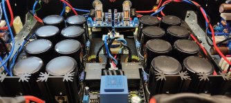
The reason Is for more power supply capacity and for possibility to be ready for 60w type with some little modding ( as irfp150 and 0,27 resistors).
Thank to Zen Mod.
Now i have to update Electric diagram (some Little adjustment) and PCB file that i will share.
The reason Is for more power supply capacity and for possibility to be ready for 60w type with some little modding ( as irfp150 and 0,27 resistors).
Thank to Zen Mod.
Now i have to update Electric diagram (some Little adjustment) and PCB file that i will share.
Here we are!
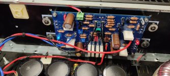
Here are some small variations that I think could be functional:
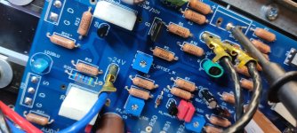
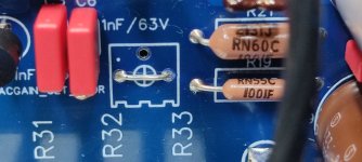
1) Replaced P1 from 1K to 500R (offset adjustment should be more accurate)
2) Replaced R17 from 47K to 68K (greater extension of the bias adjustment range)
3) Replaced R19 from 520R to 680R (greater extension of the ac gain adjustment range)
4) Introduced JP1 (Tp1 on schematic) to achieve convenience of AC GAIN adjustment. (thanks also to Rhthatcher guide 😉)
Aleph J (Zen Modded😉) vs F5 listening tests will follow.
Stay tuned!😉
As already said, here are the updated files.
I'd like to hear your listening impressions (I hope you could) on the effects of AC gain adjustment and how it can influence the final sound character.
I admit it ... I'm a fan of sound beyond the back wall!
Here are some small variations that I think could be functional:
1) Replaced P1 from 1K to 500R (offset adjustment should be more accurate)
2) Replaced R17 from 47K to 68K (greater extension of the bias adjustment range)
3) Replaced R19 from 520R to 680R (greater extension of the ac gain adjustment range)
4) Introduced JP1 (Tp1 on schematic) to achieve convenience of AC GAIN adjustment. (thanks also to Rhthatcher guide 😉)
Aleph J (Zen Modded😉) vs F5 listening tests will follow.
Stay tuned!😉
As already said, here are the updated files.
I'd like to hear your listening impressions (I hope you could) on the effects of AC gain adjustment and how it can influence the final sound character.
I admit it ... I'm a fan of sound beyond the back wall!
Attachments
Last edited:
I tell you. I had been smitten by a pair of Alephs I just finished. And they do not even have JFETs.
The sound beyond the back wall is definitely a characteristic I have been enjoying as well. I am excited to hear you're listening impressions once you get some time on it.
By the way, I don't know if it's my ears adjusting or the amps breaking in, but they get better so give it some playtime. Even with it just playing in the background while you're half listening.
I have a break-in track that I can email it to you if you like. Send me a PM if you want it.
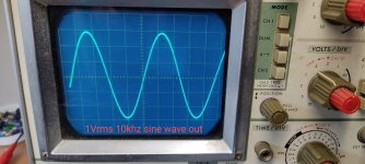
Below are some measurements made with an oscilloscope.
1) 1khz/1Vrms sine wave tone out
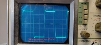
2) waveform with 1khz/1,4Vrms square wave out
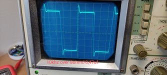
3) FR -3db 5hz-90khz detected
any advice for C feedback?
1) 1khz/1Vrms sine wave tone out
2) waveform with 1khz/1,4Vrms square wave out
3) FR -3db 5hz-90khz detected
any advice for C feedback?
Attachments
- Home
- Amplifiers
- Pass Labs
- Aleph J cascoded three incarnations