Hi!
I made three types of wiring diagrams possible only to the precious advice of Zen Mod
1) Aleph J ZEN - IRFP150 - 30W
2) Aleph J ZEN - IRFP240 - 30W
3) Aleph J ZEN - IRFP150 - 60W
They have the front end as their common denominator.
1) type 1 is a 30W and has the advantage of being able to avoid MATCHING with IRFP150 that is equal of 2 x IRFP240 inside .
2) type 2 and 3 use the same PCB layout for both 30W and 60W (only the power devices, PSU and heat sink obviously change for 60W), both 24V to 32V RAIL able to operate.
Many thanks to Zen Mod
Antonio

Hi Alex ! thanks for your advise
Diagram updated!
1) Added DZ1 5v6
2)100R JFet gate resistors change
3) P3 is still there but I only need it to fiddle around and see on the oscilloscope what happens in real time.
Immediately afterwards it will be bridged and the definitive value of R19 will be adjusted.
As soon as ready I will share both the Json file and gerber.
Antonio
Attachments
Last edited:
yes, gate stoppers needed for Q1, Q2
those are JFets
big ones are Mosfets, leave these gate resistors per Papa's schematics
those are JFets
big ones are Mosfets, leave these gate resistors per Papa's schematics
You can read about it here:
https://diyaudiostore.com/pages/universal-mounting-specification
I have made a little hole pattern template in my PCB program so that I can copy and paist it into whatever PCB I am working on. The measurements are in the link above in a PDF file.

I also had a few drill templates made in aluminum PCB material which makes driling accurate holes very convinient for non-DIYaudio heatsinks.

https://diyaudiostore.com/pages/universal-mounting-specification
I have made a little hole pattern template in my PCB program so that I can copy and paist it into whatever PCB I am working on. The measurements are in the link above in a PDF file.
I also had a few drill templates made in aluminum PCB material which makes driling accurate holes very convinient for non-DIYaudio heatsinks.
Now I understand what you meant.
To do this I use Front Panel Designer Software.
In practice, however, I will have to adapt this Aleph J to an existing F5 amplifier that I have been using for a few years.
Let's say that it is a question of having to adapt it without major efforts.
I think I'll drill the holes with a drill press.
I think I can do it easily.
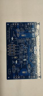
Latest version with some small adjustments to the screen printing and application notes for 60W type use.
Furthermore, the BOM list generated by EasyEDA now is correct and consistent.
Thanks again for Zen Mod and Nelson Pass of course, sorry I didn't mention him earlier.
Antonio
Furthermore, the BOM list generated by EasyEDA now is correct and consistent.
Thanks again for Zen Mod and Nelson Pass of course, sorry I didn't mention him earlier.
Antonio
Attachments
Hi guys, I remember a few years ago while I was handling the ac gain resistor, having observed right in the vicinity of the clipping that changing its value, determined the centering of the up and down shearing. So I ask you if this observation could be an alternative method for correctly adjusting the AC gain.
Go the “classic aleph” builders thread on here. You’ll find that ac gain procedure PDF and build docs including schematics for the Aleph PCBs in post #1.
https://www.diyaudio.com/community/...or-modern-ums-chassis-builders-thread.382316/
The idea is I put a jumper in line with the ac gain pot to make testing easier. You could also put sockets in for your pot/resistor to measure with the pot/resistor in and out. Then use a pot or different resistors to set the value. Solder final value into sockets.
Last edited:
ZM is dumb
for me, that always was comparing voltages across lower group (mosfets in neg rail) vs. same in upper group (Aleph CCS Mosfets)
any other approach is either too complicated to my liking, or simply above my head
exact physical arrangement, how to make easiest varying of Aleph CCS modulation resistor, that's trivial
I prefer 1pin sockets for said resistor, ensuring that you always have equal value in both channels; trimpot is working against that
- Home
- Amplifiers
- Pass Labs
- Aleph J cascoded three incarnations