So you use 2 pieces of 150 mm Seiferts on each side...
That should give you a C/W of about 0.06
This is a bit of overkill for an Aleph 5.
Even if you decide to rais the bias, as I did, your Aleph 5 won't dissipate more than 200 Watt. That means that your heatsink will reach a temp of appr. 200 x 0.06 = 12 degrees above roomtemperature. With 20 °C your amp will reach 32 °C.
This is bit low for getting up to its best sound, I think...😱
[/B]
Hihi,
I just order 4x KL271-200 for my new Aleph-X which will run on 26V-0-26V and about 7A of bias. For a total dissipation of about 364W a channel. For a max power of 164W at 7 ohm... and still 98W at 4 ohm!
Hopefully the seifert charts are right and I will get 0.07 per block for about 0.05 for two blocks a channel. Which will give about 386W * 0.05 = 20K + 20K = 40 degrees... nice...
Edwin
P.S. My 'old' Aleph 4 which 4x Sk435 of fisher runs on about 60 degrees...
Duck-Twacy said:
Its even worse, they are 200 mm high. We didnt think that the C/W value actually was that low (as on the graph).
Funny problem he 😉
Btw I use the PCBs of the Aleph4.
For an Aleph2 of 4 I would need another trafo I think (37V in stead of 30V)..
It will have a pair of strong handles (25 mm massive tube and some M10 bolts)
He Duck,
Do you have total of 2 or 4 of these KL271-200 heatsinks?
Edwin
Het wordt wel een Nederlands onderonsje, zeg 😉
Lucas, I was planning to use p2p, so thats not a problem.
I just don't need the power of an Aleph2 (actually I am planning to use the amp for the mid/high channels of a bi amped system).
Still I wonder if these Seiferts are really that good.
A 200 mm KL271 should give me between 0.08 and 0.1 K/W according to the graph. So the 150 watts of an Aleph5 would mean +12 to +15 degrees Celsius.
Of course the mosfets itself wil be hotter. I am using sil-pads, which is not as good as kapton.
Edwin, I only bought 2 KL-271 (for myself, 4 others went to Jan and Ralph). Pitty you wasn't planning to build the AlpehX then, we could have saved 5% (wow) 🙂
Still an Aleph with 8 mosfets sounds interresting. What will the specs be, around 80 watt@8 ohm using 200 watt per channel??
And do you need to change any of the values on the main PCB (assuming the same bias of the Aleph5 or Aleph2)?
Has it been done before, and how do we call it (Aleph6??)
Lucas, I was planning to use p2p, so thats not a problem.
I just don't need the power of an Aleph2 (actually I am planning to use the amp for the mid/high channels of a bi amped system).
Still I wonder if these Seiferts are really that good.
An externally hosted image should be here but it was not working when we last tested it.
A 200 mm KL271 should give me between 0.08 and 0.1 K/W according to the graph. So the 150 watts of an Aleph5 would mean +12 to +15 degrees Celsius.
Of course the mosfets itself wil be hotter. I am using sil-pads, which is not as good as kapton.
Edwin, I only bought 2 KL-271 (for myself, 4 others went to Jan and Ralph). Pitty you wasn't planning to build the AlpehX then, we could have saved 5% (wow) 🙂
Still an Aleph with 8 mosfets sounds interresting. What will the specs be, around 80 watt@8 ohm using 200 watt per channel??
And do you need to change any of the values on the main PCB (assuming the same bias of the Aleph5 or Aleph2)?
Has it been done before, and how do we call it (Aleph6??)
Duck-Twacy said:
Edwin, I only bought 2 KL-271 (for myself, 4 others went to Jan and Ralph). Pitty you wasn't planning to build the AlpehX then, we could have saved 5% (wow) 🙂
And do you need to change any of the values on the main PCB (assuming the same bias of the Aleph5 or Aleph2)?
You have to change the bias resistors (the big ones at the fet's and the ones parallel at the output). And perhaps the current source gain resistor to get back to 50% gain.
You can calculate the resistor about like this;
say 4A of total maximum output bias; this means with a gain of 50% 2A of bias on the mosfet's
2A / 4 mosfet's parallel = about 0.5A a mosfet
0.5V (voltage at gate of mosfet) / 0.5A = 1 ohm resistors!
Edwin
1 ohm, thats the same as in the Aleph5 (or 2). Of course you will need a bit "heavier" resistors than in a Aleph5. Is 5 watt still enough?
I have ordered some 1 ohm Vishays (only 12, I'm affraid).
I have ordered some 1 ohm Vishays (only 12, I'm affraid).
Hi,
when you wanna know power;
for example;
3A bias a 39V +/- rails
39 - 4 (lost at the fet) = 35
dissipation = 3 * 2 * 39 = 234W
----------------
lowest number wins, you are either voltage or current limited!
(35V^2) / 2 / 8 ohm = 76W
((3*2)A^2) / 2 * 8 ohm = 144W
-------------
(35V^2) / 2 / 4 ohm = 153W
(6A^2) / 2 * 4 ohm = 72W
-------------
so with a raised bias of 3A you get 76W at 8 ohm and 72W at 4 ohm... cool!
3A / 4 fets = 0.75 A
0.5 / 0.75 = 0.66 ohm resistors for 4 fets a piece!
hope this helps,
Edwin
(Sorry Lucas for the offtopic, you better post a new pic of your Aleph soon 😉 )
So, if I understand correctly, if I would use 8 mosfets/channel:
I)
With a bias of 2A (like a normal Aleph5) it will dissipate 2 * 2 * 39A = 156 watt/channel. (So that will still be too cool?). This is the same as a regular Aleph5?? There is no benifit?
2A bias means 1 ohm resistors at the fets?
The power calulations are a bit unclear to me (are you using P=I^2 * R = I * V ??) If I just fill in 2A in your formulas I get 76Watt and 64 at 8 ohm and 153watt and 32 watt at 4 ohm??
II)
With a bias of 3A it will dissipate 234 watt a channel and result in 76 watt/8 ohm. This requires 0.66 ohm resistors at the fets.
Anyway, this is a problem because I already bought 12 1ohm Vishay-Dales costing around 6 euro a piece.
Btw What will it mean for the 0.47ohm resistors at the output?? (Aleph5 has 4 in parallel, Aleph2 en 4 have 6 0.47 ohm resistors)
Btw Did I mention that I wil use a CLC filter using 4 2.2mH tritecs (with 0.24ohm DCR). This will influence the voltage I guess.
Duck,
for these formulas you don´t fill in 2A but the effective value of 2x 2A (at 50% ac-current-gain). Then the values will fit.
william
P.S. There must be about a hundred threads on the topic of calculating Aleph output power. How about a search😎
william
for these formulas you don´t fill in 2A but the effective value of 2x 2A (at 50% ac-current-gain). Then the values will fit.
william
P.S. There must be about a hundred threads on the topic of calculating Aleph output power. How about a search😎
william
Hi William,
Actually I just did search for "calculating power" in Pass labs forum, but didn't find anything usefull (except for AlephX).
I will search again 😉
edit.
Okay found it (searched 4 "calculate power")
http://www.diyaudio.com/forums/showthread.php?s=&threadid=4175&highlight=calculate+power
http://www.diyaudio.com/forums/showthread.php?s=&threadid=5007&highlight=calculate+power
http://www.diyaudio.com/forums/showthread.php?s=&threadid=1132&highlight=calculate+power
Anyway, this is a problem because I already bought 12 1ohm Vishay-Dales costing around 6 euro a piece.
Btw What will it mean for the 0.47ohm resistors at the output?? (Aleph5 has 4 in parallel, Aleph2 en 4 have 6 0.47 ohm resistors)
Btw Did I mention that I wil use a CLC filter using 4 2.2mH tritecs (with 0.24ohm DCR). This will influence the voltage I guess. [/B]
Hi,
When you just keep raising the number of fets from 3 to 6 you will get more bias with the same resistors 1 ohm resistors. Look at the Aleph 2 circuit. I uses 6 times 1ohm instead of 3 ohm. You get about 0.5A of bias with each fet at a Aleph 2 . So with 3 you get 1.5A and with 4 you get 2A and with 5 you get 2.5A etc. No problem here! Only your voltage rails are a bit low to get a good amount of watts at 8 ohm... sadly.. and the tritec's will only make matter worse (voltage drop over tritecs)!
But it wouldn't hurt to put in more fet's for a better and stable amp at 4 ohm and you only have to buy more of these 1 ohm resistors.
The 0.47 guys are for the current gain. You need to recalculate the CCS resistor which goes from the 0.47 guys to a 220uf and back to the transistor in the CCS. Just put in a 2K pot and take a signal generator and a rms voltage meter to put it into place (there are some good article somewhere on diyaudio). You may to have put in 1 or 2 more of these in parallel to stop them from melting and hurting the signal. no biggie...
When you look closely, you will see you are moving from the Aleph 5 to a Aleph 2 step by step...
Edwin
Then when you are all done with your amp and you think it sounds great , remove R-19 and things get about 5 times better! Be careful of the extra heat dissipated though!
Mark
Mark
Duck-Twacy said:(Sorry Lucas for the offtopic, you better post a new pic of your Aleph soon 😉 )
II)
With a bias of 3A it will dissipate 234 watt a channel and result in 76 watt/8 ohm. This requires 0.66 ohm resistors at the fets.
Anyway, this is a problem because I already bought 12 1ohm Vishay-Dales costing around 6 euro a piece.
Btw What will it mean for the 0.47ohm resistors at the output?? (Aleph5 has 4 in parallel, Aleph2 en 4 have 6 0.47 ohm resistors)
Btw Did I mention that I wil use a CLC filter using 4 2.2mH tritecs (with 0.24ohm DCR). This will influence the voltage I guess.
Hi Duck,
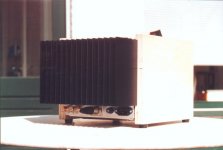
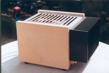
I have made some better photo's with the sides attached; now the ugly duck has found out it's a.... 🙂
But it will take some time to develope/print these and scan them 🙁
Furthermore it was I who sidetracked this topic, so never mind!
Wow, these Dales cost 6 Euro a piece
 ?
?You could of course put less pricey Intertechnik 4 Watt 2 Ohm MOX resistors in paralell with them. This wouldn't sacrifice the good sound of the Dales, bercause they still handle 66% of the current. The MOX are also quite good and precise and they cost only 60 Eurocent a piece.
Just go for the 0.66 Ohm, because it also means more efficiency.
Yes, you should go fot 6 time 0.47 then.
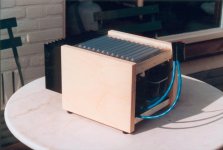
The Tritec are beauties! Almost too nice to be put in a PSU...
Maybe you should put a glassplate on top of the amplifier with some nice led throwing light on these coils...

With 0.24 Volt you will probably get a voltagedrop of about 1 Volt (I get 0.5 Volt with a 0.14 Ohm choke), so nothing to worry about.
Regards,
Lucas.
Mark A. Gulbrandsen said:Then when you are all done with your amp and you think it sounds great , remove R-19 and things get about 5 times better! Be careful of the extra heat dissipated though!
Mark
What do you mean with removing R19? What happens?
How much extra heat?
Lucas
Can't wait to see them. Did you play it a little longer? I was wondering why the red copper strip. Is it better then sticking the mosfests directly on the heatsink? Would you also do it if you would mount the mosfets p2p?Lucas_G said:
Hi Duck,
I have made some better photo's with the sides attached; now the ugly duck has found out it's a.... 🙂
But it will take some time to develope/print these and scan them 🙁
Furthermore it was I who sidetracked this topic, so never mind!
Wow, these Dales cost 6 Euro a piece
You could of course put less pricey Intertechnik 4 Watt 2 Ohm MOX resistors in paralell with them. This wouldn't sacrifice the good sound of the Dales, bercause they still handle 66% of the current. The MOX are also quite good and precise and they cost only 60 Eurocent a piece.
Just go for the 0.66 Ohm, because it also means more efficiency.
Yes, you should go fot 6 time 0.47 then.
The Tritec are beauties! Almost too nice to be put in a PSU...
Maybe you should put a glassplate on top of the amplifier with some nice led throwing light on these coils...
With 0.24 Volt you will probably get a voltagedrop of about 1 Volt (I get 0.5 Volt with a 0.14 Ohm choke), so nothing to worry about.
Regards,
Lucas.
And the Seiferts are still cool enough? Its getting warmer outside 😉
By the way what speakers are you using?
Anyway as for my amp. I guess I will attach al 8 mosfets, but maybe I start with a standard Aleph5 (so use only 6) and look what happens. I just am a bit to much a noob in electronics to redesign it to 8 mosfets (anyway if I would do that I would probably want to to it in the best way, so I would excange my trannies for higher voltage if neccessary and use different resistors if that is best. Will lose some money on that I think.
First I ordered Caddock resistors, but they took > 2 month delivery time and had a minimum order of a 100 or so (which is a bit expensive, given that they cost almost 10 euro a piece). The electronicshop than selected these Vishays which should be equally good (he said). I still havent got them, but they arrived at the shop.
The tritecs are in stead of torobars. I had already paid for the Caddocks and torobars before I heart the Caddocks were a problem, so I had some money to spare
Lucas_G said:
What do you mean with removing R19? What happens?
How much extra heat?
Lucas
without R19 you are not limiting the amout of bias which the transistor sets. It will be a maximum based on the Hfe (a transistor parameter) of the transistor. So it will not blow out of the roof, however it will raise the bias out of my head between 10 to 40% ...
Edwin
It raised both of my 2's to about .68 volts drop on the source resistors. My sinks were about twice the amount of the factory units, perhaps even a bit more than that and they were coasting as fas as heat was a factor...now they are toasty warm....I can keep my hands on them for about 15 seconds max! Still not hot enough to fry an egg though so I doubt that I'll have any semiconductor problems for a long time. I ahve not measured them with my TEK DMM temperature probe but I will and get back to you on actual device case temp and sink temp.
Interestingly, a guy came over to hear them that designs loudspeaker systems professionally and he thought they sounded fantastic with the bias giving .55 volts drop.....they now sound far more detailed and are more involving than they were. He is ging to build a tri-amped system for himself using all Aleph amplifiction.
Mark

- Status
- Not open for further replies.
- Home
- Amplifiers
- Pass Labs
- Aleph 5 playing...