I have realized a Aleph 5 amplifier but i have a problem:
With a resistive load of 8 ohm and input sinusoidal signal i see with oscilloscope a distorsion near max power over 10 khz frequency, under this frequency the output is good.
The six output mosfet are matched and the voltage across R source is similar
I have regulated current gain near at 50%
The voltage cc with voltmeter across R source of the output mosfet without input signal is near 630 mv ( bias ... ) for every mosfet
The voltage rms with voltmeter across R source of the output mosfet at max power ( before saturation ) is near 430 mv / 460 mv for every mosfet
The current rms through the load at max power is about 2.5 A at 100 hz
The power supply is +/- 31.5 volt
I try to insert photo ....
Last edited:

Max output on the load of 8 ohm 130 Hz ( yellow) and input signal ( bleu )

Saturation output on the load of 8 ohm 130 Hz ( yellow) and input signal ( bleu )

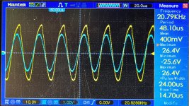
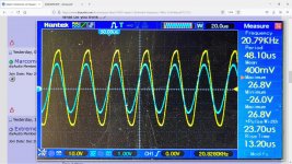
Max output on the load of 8 ohm 13 KHz with distorsion ( yellow) and input signal ( bleu )

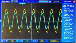
Max output on the load of 8 ohm 13 KHz before distorsion ( yellow) and input signal ( bleu )

Max output on the load of 8 ohm 19 KHz with distorsion ( yellow) and input signal ( bleu )
Thank you very much
Marco
Okay , sorry .....
Should I post them again ..?
Thank you
The output distorsion over 10 khz is correct ... ?
Thank
Marco
Look at the version with one mosfets pair less, than your's, thd vs freq.graph : Pass Labs Aleph 3 power amplifier Measurements | Stereophile.com
So at high power levels, >10KHz your measurements might be accurate, maybe someone could give some more info..
What schematic are you using ? Can you post ? I had an issue like this and it was the cap across the current stage.
Look at the version with one mosfets pair less, than your's, thd vs freq.graph : Pass Labs Aleph 3 power amplifier Measurements | Stereophile.com
So at high power levels, >10KHz your measurements might be accurate, maybe someone could give some more info..
Thank you for information ...
I don t have a thd meter

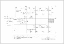
I use the schematic of the aleph5 service manual
What is the capacitor across current stage ?
In this schematic, c5 and c6, what are your values ?
Attachments
My C5 and C6 have identical value of the your schematic , now check it on the board....
The only difference is the value of R17 , in my schematic is 221 ohm , not 1k ohm ....
Marco
The only difference is the value of R17 , in my schematic is 221 ohm , not 1k ohm ....
Marco
The value of capacitor is correct.
I have try to change the value of C6:

Output max with load of 8 ohm and C 47 nf at 20 khz

Output max with load of 8 ohm and C 33 nf at 20 khz
Output max with load of 8 ohm and C 10 nf a 20 khz
With smaller value of C6 there is less distorsion e more amplitude , but a small falling edge ringing.
What Do you think ...?
Marco
I have try to change the value of C6:
Output max with load of 8 ohm and C 47 nf at 20 khz
Output max with load of 8 ohm and C 33 nf at 20 khz
Output max with load of 8 ohm and C 10 nf a 20 khz
With smaller value of C6 there is less distorsion e more amplitude , but a small falling edge ringing.
What Do you think ...?
Marco
Last edited:

Have a look at that schematics again... from the previous page.
There are 3 capacitors that will affect the high-frequency response; 2 are altering the high-frequency response at all times (C6 and C5), one only at high output levels (C4).
The only way to have a decent high-frequency waveform at 20kHz is to trim them and find the value you are happy with.
Few notes:
You may get a better high-frequency response if you bypass the C3 with something like 0.1uF... the only way to know would be to try.
Also, D3 voltage is not decoupled... try at least a 10uF cap here in parallel with D3, but make sure there are no oscillations.
And the last suggestion -> leave the speaker cables connected to the amp and place the load resistor (for testing) at the end of the speaker cables (remove the speakers). The speaker cable impedance will play a major factor, especially at those high frequencies. Also, make sure the probe is set to 10:1
No human ear wants to hear >10kHz at FULL power. All speech/music falls off in the highs, above 2khZ or rarely 5kHz. Yes, even cymbal-heavy disco.
So while the increase of distortion may be technically interesting it does not hurt the music.
So while the increase of distortion may be technically interesting it does not hurt the music.
I recall something about an Aleph current source clipping mod, maybe this is what you're seeing?
Aleph Clipping Mod
Sadly the pics are gone, but as far as I recall, it really was just a Zener across the current source transistor.
Aleph Clipping Mod
Sadly the pics are gone, but as far as I recall, it really was just a Zener across the current source transistor.
Post #84 has a copy of the Aleph modification write-up:
https://www.diyaudio.com/forums/pas...semisouth-j2-clone-monster-9.html#post2377087
https://www.diyaudio.com/forums/pas...semisouth-j2-clone-monster-9.html#post2377087
Why Bothering?
Do you listen all times at 87Watts output power. I doubt that..
What you see in the third Thumbnail of distortion is about .2% @ Full Load
But some here already gave you the right answer..
I have insert image as at attachments 🙂
Do you listen all times at 87Watts output power. I doubt that..
What you see in the third Thumbnail of distortion is about .2% @ Full Load
But some here already gave you the right answer..
thanks for the valuable explanations and advice.
I understood that it is not an audible problem, but I try to improve .....
Now I will make changes and then I will tell you the way they did
Marco
I understood that it is not an audible problem, but I try to improve .....
Now I will make changes and then I will tell you the way they did
Marco
It's not an Error of the AMPLIFIER
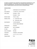
My Friend, what you are trying to do, is out of specifications of this Amplifier..
The specs you can find as picture and if you know how to calculate output power, the you will see that you have driven the Amp into Clipping in negative half wave and then you do not need to be surprised when the positive half wave distorts at over 10K..
Read the Spec, then check out your Pics, with the max output power RMS, which I can see in there, and if you still think that the AMP run out of Spec and produces too much Distortion, then you might start to change..whatever you like..
But in this case it's the Error of the USER and not an ERROR OF the DESIGNER OR THE AMPLIFIER.
You need to understand that every Amplifier has it's limits. These Limits are listed in the Picture I placed,
According to your added Screenshots or photographs, it shows to me, that you driven that amp beyond its limits.. DO not MODIFY something when there is no need to Modify.
To feed 60 Watts into 8 Ohms, the amplifier needs to output 22Volts RMS
Your Photograph shows 26.8 volts.. so now reduce input volume so that it shows 22VoltsRMS and then if it still shows Distortions, place another Photograph here..
Attachments
Last edited:
- Home
- Amplifiers
- Pass Labs
- Aleph 5 distorsion on frequency over 10KHZ