Debug - step 2
I have now connected the current source back to the differential pair. The originally selected parts are back in place.
I have removed R7 and C8, as well as Q4 and C6 to isolate the diff pair. Z1 - Z4 are not there either.
Then, by using a small clip I have connected node R7-R10 with node R2-R9. With this, the diff pair is set up as a current mirror and both fets should behave identical.
I have applied +/- 55V on the rails
The total current sunk by the circuit is now 29mA. The additional 6mA is clearly the supply for Z5-R13.
V_R11 = 5.171V --> 23.3mA
Vgs_Q1 = 3.951V
Vgs_Q2 = 3.951V
V_R14 = 4.249V --> 10.8mA
This leaves a 1.7mA offset between the two branches in the diff pair. I'm not the expert today, but I believe this is within tolerances.
Next step is the main current source
I'm measuring the circuit around the main current source now. The high-current section is reduced to a 1/6 scaled down test setup, where Q6-Q11 is replaced with a single IRF250 mosfet in a TO3 case.
All other values are identical. Q5 is a ZTX450 device
The current sourced is a bit on the low side... around 400mA and slowly dropping as the heatsink warms up. Voltage across R40-45 (now a single wirewound 1 ohm resistor) is 0.4V. That seems to be in line with Ohm's law fortunately, but again, it appears a bit on the low side.
Vce_Q5 = 4.38V
Vgs_Q6-Q11 = 3.96V
V_R20 = 175mV (slowly climbing as heatsink warms up) --> 175uA
V_R21 = 0V
V_R19 = 13.4V --> 240uA
V_R18 = 10.9V --> 7.2mA
V_R17 = 35.8V --> 7.5mA
This would mean the current amplification in Q5 is 7.2mA / 415uA = 17.34
According to theZetex datasheet this doesn't really translate to the correct hfe figures mentioned here.
Now I would be tempted to conclude Q5 is defective. However, if I replace Q5 with a fresh device, the measurements don't change....
What is going on?
toss datasheets in junk box
all you need with Alephs is knowing few physical constants .....
anyway ( dunno is it against new rules about Papa's IP ; if yes - MODS PLEASE DELETE IT and leave note , ) find enclosed great pdf file , for reference
what's going on - if you disconnect R19 ( in A2 original schematic) ;
that way you'll have max possible current from Aleph CCS ;
if that's correct - just fiddle with R19 value , and set desired current
it's best to have R19 comprissed of one fixed resistor and multiturn pot
same for R11 ;
than you can fiddle iteratively with these two pots and set all needed param's .
later - you can replace res+pot combo with fixed resistor ..... or leave them as is .
( btw . ya realized what "Fugly ! " is ? )
Attachments
* datasheet tossed in paper recycle bin *
If R19 is removed, current sourced goes up to approx. 660mA
Vce_Q5 = 4.72V
Vgs_Q6 = 4.05V
I understand I can tweak this value... Good point. But does this explain the failure I have, and the behaviour shown in the previously posted scope screenshot?
Fugly = Hollywood term for "terrible?" (in fashion)
Dude... My amp is NOT fugly!  Exaggerated yes.... but fugly? 🙂
BTW: you can remove pdf... I have it now. Next time send email
If R19 is removed, current sourced goes up to approx. 660mA
Vce_Q5 = 4.72V
Vgs_Q6 = 4.05V
I understand I can tweak this value... Good point. But does this explain the failure I have, and the behaviour shown in the previously posted scope screenshot?
Fugly = Hollywood term for "terrible?" (in fashion)
Dude... My amp is NOT fugly!
Exaggerated yes.... but fugly? 🙂BTW: you can remove pdf... I have it now. Next time send email
I'm little bit lost in components labels on your Aleph...May I ask you put here schematics of your construction and let me have look (please don't forget components labels..as you used them in description of your's issue). Or you can send me it over email t_majerovic@yahoo.co.uk
Bakmeel said:* datasheet tossed in paper recycle bin *
If R19 is removed, current sourced goes up to approx. 660mA
Vce_Q5 = 4.72V
Vgs_Q6 = 4.05V
660mA is good - that shows that ZTX's Ube is ~ 0,66V ( that's one of physical constants Papa described as important)
Bakmeel said:
I understand I can tweak this value... Good point. But does this explain the failure I have, and the behaviour shown in the previously posted scope screenshot?
you probably had some damaged part (mostly thinking about noise issue ) ; anyway - nonsymmetrical clipping can be result of few things - unfortunate value of R19 and unfortunate value of AC gain in Aleph CCS ;
when you finish fiddling with R121 and R19 values , you must set value of R21 - responsible for Aleph CCS AC gain ;
you'll find that info easy in numerous threads ....... same as in Algar_emi's pdf ...
it's easy to go south with all explanations , but I think that's pretty simple view on that issue - if you set R21 value that you have same Vac readings across R40 and R46 , then upper and lower half of amp have same contribution to output sine ......... and then Aleph CCS's AC gain is funny called 50%
Bakmeel said:
Fugly = Hollywood term for "terrible?" (in fashion)
Dude... My amp is NOT fugly!
BTW: you can remove pdf... I have it now. Next time send email
"Fugly!" - Chokyfied "dude , that's really something !"
everyone sez - " nice , awesome , goodlooking , neat , etc " .......
but that's just that ........
when I write "fugly!" , I don't think that piece in case is just another "that " ......
Zen Mod said:
you probably had some damaged part (mostly thinking about noise issue ) ; anyway - nonsymmetrical clipping can be result of few things - unfortunate value of R19 and unfortunate value of AC gain in Aleph CCS ;
when you finish fiddling with R121 and R19 values , you must set value of R21 - responsible for Aleph CCS AC gain ;
you'll find that info easy in numerous threads ....... same as in Algar_emi's pdf ...
it's easy to go south with all explanations , but I think that's pretty simple view on that issue - if you set R21 value that you have same Vac readings across R40 and R46 , then upper and lower half of amp have same contribution to output sine ......... and then Aleph CCS's AC gain is funny called 50%
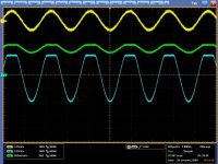
Makes sense yes... I'll do the fiddling tomorrow... Here's another scope screenshot again.
- Yellow = input
- Blue = output
- Green = current trough R40 = CCS current
"Fugly!" - Chokyfied "dude , that's really something !"
everyone sez - " nice , awesome , goodlooking , neat , etc " .......
but that's just that ........
when I write "fugly!" , I don't think that piece in case is just another "that " ......
Thanks

Attachments
Bakmeel said:
Makes sense yes... I'll do the fiddling tomorrow... Here's another scope screenshot again.
- Yellow = input
- Blue = output
- Green = current trough R40 = CCS current
in your present test - seems that Aleph CCS is starving on +/-20V
with A2 PSU it will be better .
for now - in test bed with +/-20V remove R19 , and measure again
I can bet that will be better
edit :
you didn't inform us about noise issue .... is it gone ?
Zen Mod said:
in your present test - seems that Aleph CCS is starving on +/-20V
with A2 PSU it will be better .
you didn't inform us about noise issue .... is it gone ?
The voltage was +/- 55V. I'll have another look tomorrow. With no input, there is a few mV DC on the output... didn't really look for noise.
What I find interesting here is the current from the CCS is modulated around its nominal DC value... approx. 400mA. If I remove the input, the CCS correctly returns to that value.
Then, I was thinking maybe there is to much AC gain in the CCS and Vbe clips to 0.66V. If that were true, the current should als be seen clipping but at 660mA. Now, it only clips at about 450mA.
Anyway, I've left the thing at work for the night. I'll check and fiddle tomorrow.
Zen Mod said:
"Fugly!" - Chokyfied "dude , that's really something !"
everyone sez - " nice , awesome , goodlooking , neat , etc " .......
but that's just that ........
when I write "fugly!" , I don't think that piece in case is just another "that " ......
I have to admit i was a bit puzzled when you labeled his amps as fugly, because fugly is also used to describe something that's past ugly.
Anyways, sorry to hear about your amp, afraid I haven't got much to contribute in this matter, but I wish you good luck in your troubleshooting.
My hints for you...
So I'm back and was looking to your issue. I guess that:
both Alephs 2 are identical (circuit, PCB, values, components)
you checked all semiconductors and maybe passives (you didn't tell us that you find something broken/defected)
I made some simulations in TINA with reduced output stage to one IRFP pair (one transistor positive rail and second transistor on negative rail). Amplifier starts clip on output with 10R load somewhere from 390mV of input signal (peak to peak, 1kHz). But I think that it is normal behavior once you reduced current given by current source in output stage.
Upon information which I received from you and summarized them, my recommendation is:
Assemble all output mosfets back (under condition that no one is defected)
Check conductivity of paths on PCBs and wires which makes connection to power mosfet board(s) (focus to positive rail)
If failure persist...measure voltages across whole amplifier (with applied full power supply voltage and resistive load on output) and send to me back.
I curious to news from you
Good luck
Tomas
Attachments

Supportcrew is in full "F5" modus for statusupdates. So glad to read you guys make progress on solving this issue...
Re: Full current gain
Yes, it is normal and logical. Remove R19 causes increase current given by current source then amplifier is able to deliver more voltage to 10R resistor connected as load. I think that there is not hidden problem… To measure reduced output use higher resistance for load….Otherwise you generate another issue: clipping on output…..
Bakmeel said:Lookie Lookie!
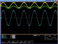
This is an interesting bit... I have disconnected R19 again to get max CCS output....
Voila!
Yellow = Input
Blue = Output
Green = CCS output (through R40)
So, too little DC current gain or too much AC gain?
Yes, it is normal and logical. Remove R19 causes increase current given by current source then amplifier is able to deliver more voltage to 10R resistor connected as load. I think that there is not hidden problem… To measure reduced output use higher resistance for load….Otherwise you generate another issue: clipping on output…..
Re: Full current gain
first - correct R19 that you have Papa's values of Iq ......... 0,5A per each mosfet
fiddle with R11 in same time to preserve zero offset on output
then check AC gain
Bakmeel said:Lookie Lookie!
This is an interesting bit... I have disconnected R19 again to get max CCS output....
Voila!
Yellow = Input
Blue = Output
Green = CCS output (through R40)
So, too little DC current gain or too much AC gain?
first - correct R19 that you have Papa's values of Iq ......... 0,5A per each mosfet
fiddle with R11 in same time to preserve zero offset on output
then check AC gain
Low Frequency settle
I agree. Vice versa, if I would leave the setup like this, then I'd see the clipping again as soon as the input exceeds 1.5V or so. I know from the other board they can handle up to 5Vp-p before I see clipping. Then the clipping is also symmetrical, clearly indicating the amp is "out of breath"
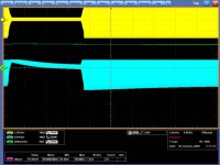
Please have a look at this screenshot. It is a long-stretch recording of the amp. Colors are as above. I change the input amplitude rapidly between 1.7Vp-p and 170mVp-p. Now, note that here I have disconnected R21. It removes the AC modulation in the CCS, but this has no effect on the amp's "faulty" behaviour.
Notice how the DC offset changes very slowly when the amplitude is changed. Apparantly the diff pair is very slow in correcting the DC error caused by the clipping... I suppose this is due to the low-pass filtering in the feedback R7/C5?
t_majerovic said:
Yes, it is normal and logical. Remove R19 causes increase current given by current source then amplifier is able to deliver more voltage to 10R resistor connected as load. I think that there is not hidden problem… To measure reduced output use higher resistance for load….Otherwise you generate another issue clipping on output…..
I agree. Vice versa, if I would leave the setup like this, then I'd see the clipping again as soon as the input exceeds 1.5V or so. I know from the other board they can handle up to 5Vp-p before I see clipping. Then the clipping is also symmetrical, clearly indicating the amp is "out of breath"
Please have a look at this screenshot. It is a long-stretch recording of the amp. Colors are as above. I change the input amplitude rapidly between 1.7Vp-p and 170mVp-p. Now, note that here I have disconnected R21. It removes the AC modulation in the CCS, but this has no effect on the amp's "faulty" behaviour.
Notice how the DC offset changes very slowly when the amplitude is changed. Apparantly the diff pair is very slow in correcting the DC error caused by the clipping... I suppose this is due to the low-pass filtering in the feedback R7/C5?
Attachments
Re: Low Frequency settle
short C5
Bakmeel said:
.... I suppose this is due to the low-pass filtering in the feedback R7/C5?
short C5
Re: Low Frequency settle
Done... low frequency behaviour = gone. Clipping remains, and there is 400mV DC on the output.
I've tested all electrolytics in the board (C5, C9, C10) none are shorted, in-circuit test gives approx. 230uF for each.
Zen Mod said:
short C5
Done... low frequency behaviour = gone. Clipping remains, and there is 400mV DC on the output.
I've tested all electrolytics in the board (C5, C9, C10) none are shorted, in-circuit test gives approx. 230uF for each.
Re: Re: Low Frequency settle
now - read what I wrote in post #96 ;
when you check all , inform us what results are
😉
Bakmeel said:
Done... low frequency behaviour = gone. Clipping remains, and there is 400mV DC on the output.
I've tested all electrolytics in the board (C5, C9, C10) none are shorted, in-circuit test gives approx. 230uF for each.
now - read what I wrote in post #96 ;
when you check all , inform us what results are
😉
- Status
- Not open for further replies.
- Home
- Amplifiers
- Pass Labs
- Aleph 2 - The Final Build