Congrats dliscomb! I have always been happy with the sound of this preamp as well.
Do you have plans for your streamer yet? Raspberry Pi or something different? I’m contemplating a Raspberry Pi, Intel NUC, or mini ATX custom build.
Do you have plans for your streamer yet? Raspberry Pi or something different? I’m contemplating a Raspberry Pi, Intel NUC, or mini ATX custom build.
Streamer build
TBH, I hadn't really thought about it until now.
After making the MoFo, it made sense to move on to the pre amp.
I mean; my AKSA-Lender still isn't done, needing a case and the proper voltage.
In any case, it made sense to try for the next stage.
I'll start that investigation when the preamp has a proper enclosure.
Kind regards,
drew
Bravo Drew!!
Wasn’t it worth the wait? 😛
Enjoy your ALP/MoFo combo!
Yes great sound. Very satisfying build for.sure. Can't wait to hear how my SONY "monkey coffins" sound with it, compared to my Sansui 5000x.
I've been considering the NuTube as an alternative, because I've never (knowingly) heard a tube amp b4.
Kind regards,
Drew
I have power supply questions. The end goal for The AKSA lender is to drive an F4. But in the meantime, It will be driving an F5 Turbo biased to 80 class A watts/channel.
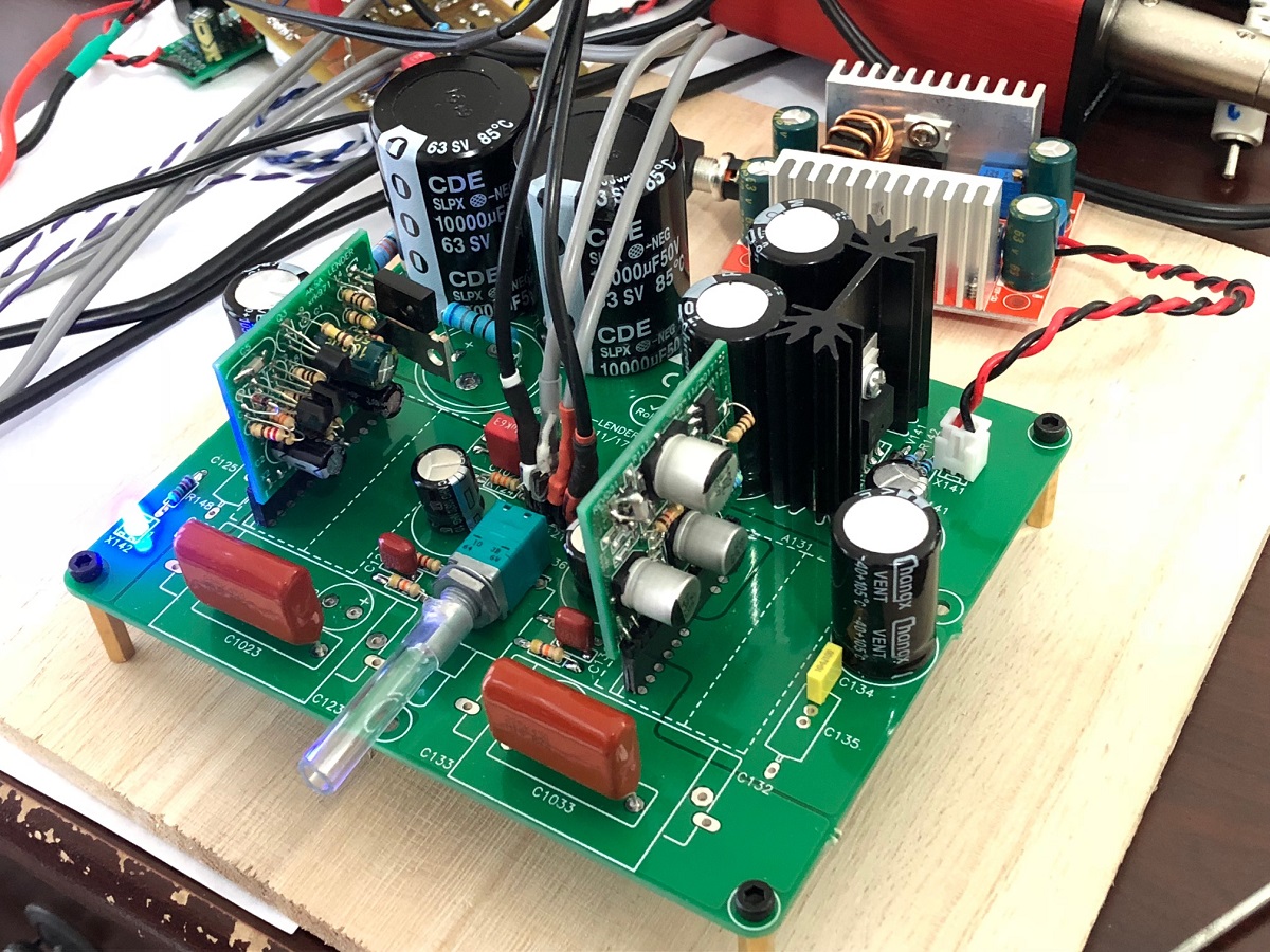
The boards I have are marked T141 and T142, and I recall reading *somewhere* about using Talema transormers. I even recall looking for them a couple years back, but somehow, I've gotten lost.....
And, the BOM does not identify either T141 or T142.
could someone point me in the right direction please?
An easy way to find something specific, is to put Google search to use. If you enter "AKSA's Lender Preamp with 40Vpp Output " or talema or site:diyaudio.com into Google, you'll probably find what you're after.
Try it here
.
.
Try it here
.
.
The boards I have are marked T141 and T142, and I recall reading *somewhere* about using Talema transormers. I even recall looking for them a couple years back, but somehow, I've gotten lost.....
And, the BOM does not identify either T141 or T142.
could someone point me in the right direction please?
The AKSA Lender Preamp doesn’t have provisions for onboard transformers.
The Yarra preamp uses a pair of Talema Trafos, 15va or 25va, 60mm x 60mm size. Example: Blocked
Omg, that is hilarious.... I bought the yarra boards a while ago, along with the case. And here I am on the wrong thread, with carts full of the wrong parts all over the world!
Sorry folks!
Sorry folks!
Lost
I am at a loss. I have built the preamp but I am getting wicked amounts of dc at turn on, something like 12v at the output. This then declines into the millivolt range over 30 seconds or so. If left on long enough it warms up and the output dc drops to a steady 1mv or less.
Where do I begin to look for the cause of this?
I haven't read through all the 133 preceding pages.
Is the pcb layout essential? Will using a veroboard (or p-t-p) be ok?
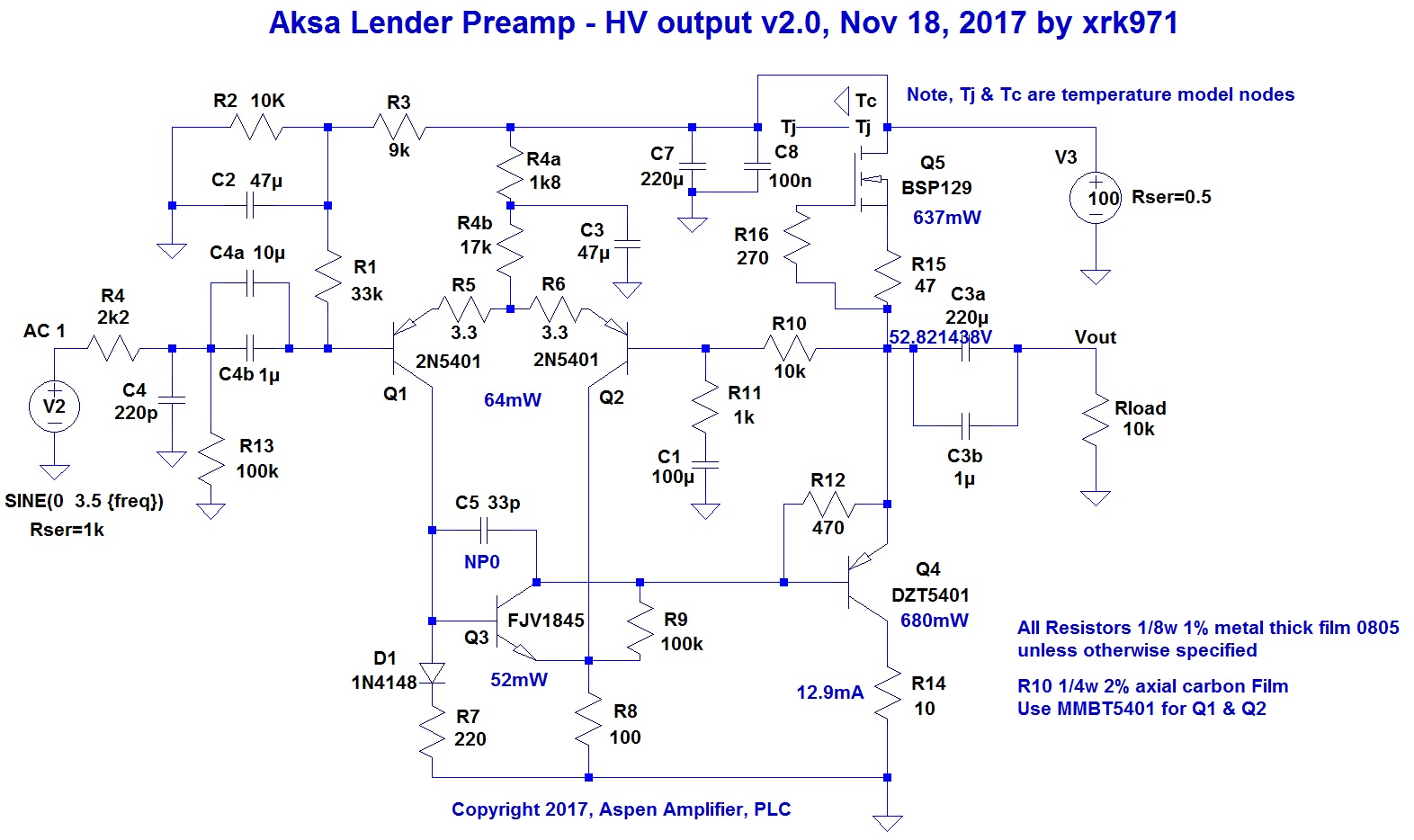
V3 is the power supply? Unipolar 100V?
Where can I find the schematic for that?
Is the pcb layout essential? Will using a veroboard (or p-t-p) be ok?
V3 is the power supply? Unipolar 100V?
Where can I find the schematic for that?
No schematic- you need to make your own. I use DC/DC converter and CLC filter and cap Mx filter followed by CRCRC filter. That’s provided in the design.
#noobAlert
@xrk971, what'd you do there with the final filter, in C148?
CRCR*R*?
Hm. 2x 10KuF instead of 3x 4.7KuF gives bigger buckets, albeit fewer of them.
Do you notice any difference from the "stock" CRCRC implementation?
Kind regards,
Drew
@xrk971, what'd you do there with the final filter, in C148?
CRCR*R*?
Hm. 2x 10KuF instead of 3x 4.7KuF gives bigger buckets, albeit fewer of them.
Do you notice any difference from the "stock" CRCRC implementation?
Kind regards,
Drew
No schematic- you need to make your own. I use DC/DC converter and CLC filter and cap Mx filter followed by CRCRC filter. That’s provided in the design.
thanks for that. I've started to read the 133 pages. There's are plenty of info dispersed within those pages. I didn't think those buck converters were quiet enough for us in the golden ear crowd, but happy to be proved wrong.
Well it finally happened, after 50 years of building electronic stuff I put a electrolytic capacitor in backwards, didn’t hurt anything as I slowly ramped power up watching an amp meter. Not to look a gift horse in the mouth ( not sure where that saying came from) I would have caught it if the polarity marking had not been covered by the capacitor ( hint hint). Also my pre amp boards powered up with no smoke however do not work. I verified no solder bridges or cold joints and I always verify resistors to 5 digits ( critical positions buy extra and match). I did measure and match the bc560c for hfe but did not verify rest of semiconductors. Since both boards act the same I suspect I may have sourced some fakes.
Bill
Bill
Most power amps are driven to full power at about 2Vpp input or so. What is the value of that much voltage swing in a preamp? You could ever use it all.
0dB gain amplifiers like MoFo, F4, LuFo, etc... need a preamplifier that swings big voltage like the Aksa Lender to drive them properly.
You are correct that an amplifier with 26-28dB of gain built in would not require this much oomph.
You are correct that an amplifier with 26-28dB of gain built in would not require this much oomph.
Nelson Pass mentioned he felt full range speakers benefited being driven by a current buffer as opposed to standard amp. Since I happen to have a pair of stereo F4 amps and a pair of Frugal horns I thought I would see for myself. Once you have listened to a full range speaker there is a purity to them.
did I miss some thing when you use a DN2540NS instead of bd139 are the pinouts different? I seam to have 48v going to the gate.
Bill
Bill
- Home
- Source & Line
- Analog Line Level
- AKSA's Lender Preamp with 40Vpp Output