I just hooked up my Aksa Lender (mini MELF SMT version) to my MoFo amp and 0.53x Karlsonators with dual 3FE25 drivers. Great combo - the soundstage and imaging are superb. Something neat about a single MOSFET SE Class A amp with no global feedback. I have not listened to the Aksa Lender and MoFo combo in a while. It’s very nice if you can live with 11Wrms.
You need to use a CLC filter between your ACA PSU and the DC step up. Else you may get some noise back to your ACA amp. Better to use a separate 12v 1000mA or 24v 500mA Class 2 transformer wall wart commonly seen on routers, modems etc.
I really want to minimise external junk, so I might look at one of the smaller meanwell SMPSs, they do 48v output versions and the 15w would tuck in there nicely (the 25w being a squeeze), would just the supplied CLC filter be fine between the SMPS and main board.
...would just the supplied CLC filter be fine between the SMPS and main board.
Hi Bill
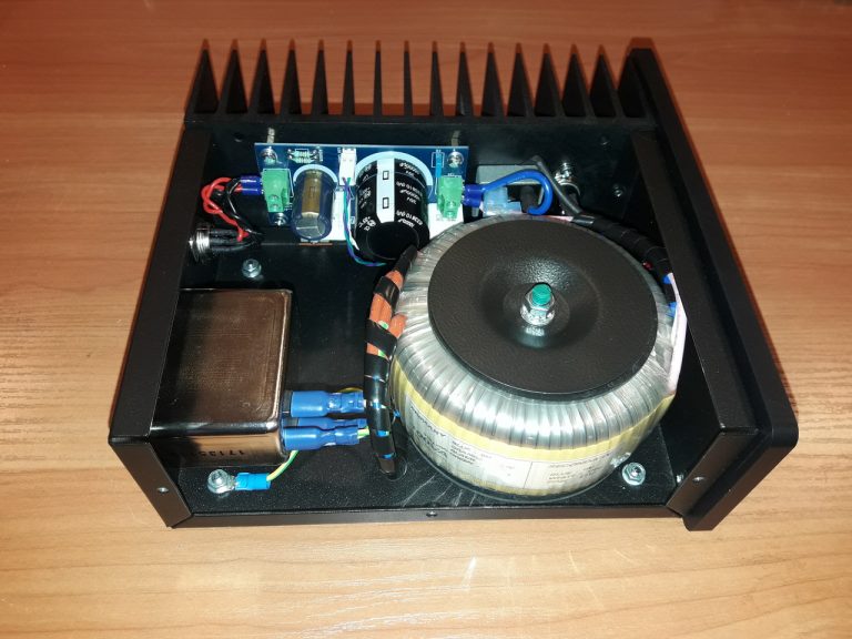
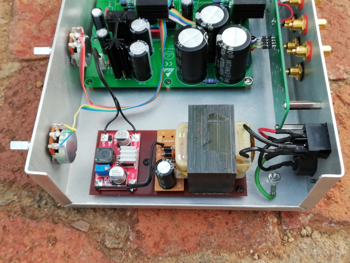
I didn't even use the supplied CLC filter. Just a transformer with it's rectifier board (from a router PSU) and the DC-DC step-up. There is no noticeable hum on my 94dB speakers.
I may replace the transformer with a LRS-15-12 Meanwell. The transformer gets very hot.
PS The pictures of your ACA are not available in the ACA thread. Please post again. I'd love to see how it came out.
Last edited:
Linear Power Supply Unit L-100
Just a moment ago I was visiting the Aleksandar store and I see two new product.
Linear Power Supply Unit L-100 €178 - €200 + shipping from Bulgary (EU)
Linear Power Supply Unit L-100 | ATL Audio Ltd.
The second product: HIGH-POWER DC Blocker Trap Filter – Assembled in Case | ATL Audio Ltd.
HIGH-POWER DC Blocker Trap Filter – Assembled Device | ATL Audio Ltd.
I may replace the transformer with a LRS-15-12 Meanwell. The transformer gets very hot.
Just a moment ago I was visiting the Aleksandar store and I see two new product.
Linear Power Supply Unit L-100 €178 - €200 + shipping from Bulgary (EU)
Linear Power Supply Unit L-100 | ATL Audio Ltd.
Specificatios:
– Input voltage: AC 115V or AC230V (according to the destination country or user request)
– Output voltage: DC 12V/19V/24V (user-defined values are also available upon request)
– User selectable option for 8mm. aluminum front panel (black anodized)
– Dimensions: 220x220x75 mm.
– Transformer Power: 100VA
– Weight: about 4.5kg
– Output DC cable with barrel jack 5.5/2/5 mm. (OD/ID)
– Possibility for different output connectors upon customer’s request
– Built-in trigger-type overcurrent protection (in case of protection’s engagement the unit must be turned off for a while in order to recover its normal work)
– Built-in trigger-type overheating protection preventing the unit from burning in case of serious malfunction
– Common mode AC filter on the input of the AC supply voltage
– Front panel LED
Schematic description
The regulator has all-discrete topology. No Operational Amplifiers are used. This allows complete design control over all operating points and parameters for superior performance. Low noise, high PSRR.
There is a bridge rectifier block on the input which is filtered with a massive electrolytic capacitor on the output. This greatly reduce the ripple charge voltage and hence helps for better output filtering...
Measurements
Measurements of DC and AC voltages were taken with Keithley 2015 Multimeter while the spectrum plots were drawn using RTX 6001 Audio Analyser. The obtained results are as follows:
– Line regulation (AC input voltage between 216 – 235 V): 0.05%
– Load regulation (DC output current between 0 – 4.5 A): 0.06%
– Output AC ripple voltage when loaded with real load (Lenovo ThinkStation M92p): 4.2 mV RMS
– Measured Power Supply Rejection Ratio (PSRR): -120 dBV for fundamental harmonic (100 Hz)
The second product: HIGH-POWER DC Blocker Trap Filter – Assembled in Case | ATL Audio Ltd.
HIGH-POWER DC Blocker Trap Filter – Assembled Device | ATL Audio Ltd.
Last edited:
Hi Bill
I didn't even use the supplied CLC filter. Just a transformer with it's rectifier board (from a router PSU) and the DC-DC step-up. There is no noticeable hum on my 94dB speakers.
I may replace the transformer with a LRS-15-12 Meanwell. The transformer gets very hot.
PS The pictures of your ACA are not available in the ACA thread. Please post again. I'd love to see how it came out.
I'm looking at the Meanwell RS-15-48 initially. 43-52v variable output 313mA limit and fully loaded I think it quotes 200mv P-P maximum noise (I've used 2 meanwell supplies and in practice I have never seen them be that bad). I would hope with the CLC filter it would be ok and I prefer the idea of going straight to my desired voltage rather than another step up.
I will update my ACA progress over Xmas as I should have the thing complete, I'm struggling to find the time to finish the chassis (should have just bought one from hifi2000 and not mucked about trying to build one for next to nothing).
(should have just bought one from hifi2000 and not mucked about trying to build one for next to nothing).
Is there a good hifi2000 for the AKSA to match the Amp Camp Amp? Using the power transformer outside the AKSA.
Looking at this one, but don't know if it is ok and if it matches the Amp.
Galaxy GX243 230 x 230 x 40 mm 10mm BLACK front panel
Mini Dissipante 2U 200mm frontale 10mm NERO coperchi in alluminio 2mm e retro 3mm
I'm sure a quick email to HiFi2000 to ask if they have a suitable match would get you an answer. If you see my case on the previous page, I'm using a 75mm high front panel cut from 10mm aluminium (to match my ACA case which is similar to the DIYAudio one). I'm then using aluminium extrusion for the sides from these guys:
Custom Electronics Box UnioBox 66 - Lincoln Binns
the Uniobox-66 extrusion is basically cut to length (I'm doing 200mm), then the front and back panels cut from 10mm and 6mm aluminium plate bolt through with M4 fixings into the extrusion. I then have a 2mm thick top and 3mm thick base that slot into the extrusion to make a case. Once complete the back and sides will be powder coated matt black and the fronts should be anodised a very dark grey.
I've gone with a 10mm thick front and 100mm high by 250mm wide for my ACA, the heatsinks were about 180mm long as they were what I had, I wanted to make the ASKA slightly shorter but the same width to stack and deeper. I've made the front panel of the ASKA 250mm wide but the body sits about 30mm in at each side to give good clearance above the ACA heatsinks for better airflow and cooling. I may yet sit the ACA on a matching plinth to raise that (and the plinth might be a 2" high phono pre amp) and get better airflow under it.
Once done I will post piccies.
Yep, will email HiFi2000 when I know the height of the AKSA inside requirement. Would prefer the preamp box same design, width and approximately length but lower height than the Amp.
Would like the preamp below the Amp. Probably doesn't need heatsinks on the preamp?
Would like the preamp below the Amp. Probably doesn't need heatsinks on the preamp?
C4a and C4b form quite a resonant notch filter at the input and/or an antenna somewhere around 4MHz. I avoid doing this with bypass capacitors because the resonant spike can cause oscillation. If the input is grounded or has a low source impedance it could mess with the loop gain as well. It could be a non-issue but I avoid doing this on principle. If you don't want to remove one of the capacitors you can add some series resistance to one of them. 1 ohm would be enough.
For input signals it behaves like a notch filter but for RF it is a resonant antenna.
C7/C8 could be an issue as well. Usually if you use 1uF instead of 100nF the ESR of a 100uF cap will be enough to control the resonance pretty well. The ESL of a 1uF polyester cap will not be an issue at all, the 100uF cap alone doesn't have enough ESL to cause issues anyway. Technically there is no need to have a low ESL/ESR bypass here as the lytic has low enough ESL.
Last edited:
Looking for buying the caps: C146, C147, C148. They are 4700uf/63v/UKW Can't find them for sale. Can find C1046, C1047, C1048 on the list: 3300uf/63v/UVR
Does it make a difference between them from 4700uf to 3300uf?
Does it make a difference between them from 4700uf to 3300uf?
Hi.
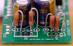
Last night soldered some resistors to it, and now noticed they are correct resistors but some of them are not set to the circles on the pcb.
Does that make a problem?
If there’s no mechanical problem ( and it doesn’t seem to be one) then it is fine
C4a and C4b form quite a resonant notch filter at the input and/or an antenna somewhere around 4MHz. I avoid doing this with bypass capacitors because the resonant spike can cause oscillation. If the input is grounded or has a low source impedance it could mess with the loop gain as well. It could be a non-issue but I avoid doing this on principle. If you don't want to remove one of the capacitors you can add some series resistance to one of them. 1 ohm would be enough.
For input signals it behaves like a notch filter but for RF it is a resonant antenna.
C7/C8 could be an issue as well. Usually if you use 1uF instead of 100nF the ESR of a 100uF cap will be enough to control the resonance pretty well. The ESL of a 1uF polyester cap will not be an issue at all, the 100uF cap alone doesn't have enough ESL to cause issues anyway. Technically there is no need to have a low ESL/ESR bypass here as the lytic has low enough ESL.
Thanks for this observation! Sounds like good reason to avoid bypassing then - I have heard people say it causes loss of resolution. But avoidance of resonant filter/antenna is an important reason. Adding 1R is an easy thing to do too.
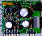
What should be installed there for #10?
Have found two circuits, one says 10k0, and the other one says 8k2 (that's the circuit just above)
I'm not an electronic engineer, would like some help if anyone can help me not make bad mistakes. Here or via the private messages.
Have found two circuits, one says 10k0, and the other one says 8k2 (that's the circuit just above)
I'm not an electronic engineer, would like some help if anyone can help me not make bad mistakes. Here or via the private messages.
Here is schematic for TH board:
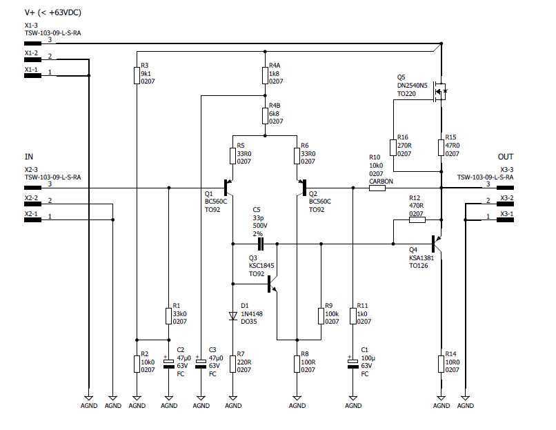
R10 is the feedback cap. Use a good quality metal thin film or carbon film here. Depending on how much gain you want set Gain=(R10+R11)/R11.
If you want to use as a normal preamp to drive, say, a 15dB Pass Class A amp like an ACA, you will want about 15dB. If you want an amp to drive a full 40Vpp to drive a 0dB amp like and F4, you will want about 27dB to 30dB gain.
In the schematic I have 10k for R10 and 1k for R11 so gain is (10+1)/1=11 or 20.8dB
Hugh recently reminded me that ideally, the input impedance on left transistor and feedback impedance should be about the same. So should leave R10=33k and play with R11 to get desired gain. So assuming you want about 15dB to drive ACA or F5, then use R10=33k and R11=6k8 and gain will be 15.3dB.
Last edited:
Thanks xrk971
So previously for the ACA, the gain for running from the Lender was set at 15db with R11 at 2k2, and the R10 at standard 10k0.
Now should be better if it was done with the R11 at 6k8, and the R10 set at 33k.
Both versions should give about 15db, but the newer version would be better.
For the R10, should still have those good quality metal thin film or carbon film resistors.
Need some more resistors 🙂
Irf510 is fine. If you don’t have metal thin film or carbon film go ahead and use what you have for now to get music. Change later. It’s a minor effect. Same with 33k and 10k on feedback R10. Use what you have to get sound and listen - it will work fine until your new ones come in.
- Home
- Source & Line
- Analog Line Level
- AKSA's Lender Preamp with 40Vpp Output