For input selector switch, the Lorlin 4 position 3 Pole rotary switch works best. RS #665-203. Make sure to get the through hole variant.
The input selector board only has one output and four inputs. The way the board is designed also had me thinking there are two outputs. ....
Thanks for the info. If I wanted to add a second output for the subwoofer is it as simple as wiring in another outlet from the output side of the volume control? I realize this would be before the pre but I don't think the subwoofer plate amp needs the gain that the pre adds. Any impedance issues? Subwoofer has a 10k input impedance.
For input selector switch, the Lorlin 4 position 3 Pole rotary switch works best. RS #665-203. Make sure to get the through hole variant.
The RS sites seem to be worldwide except US. The Lorlin part number is CK1051 FWIW - mainly putting this here so I can find it again.
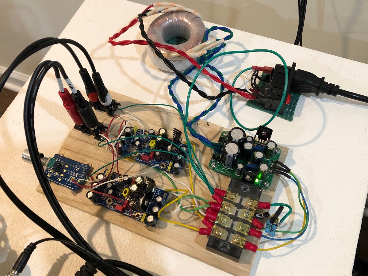
As a test to check to see if it can work, I packaged the Melbourne duughterboards into their own standalone preamp with a cap multiplier PSU.
New thread on the Melbourne Pre-Amp (and headphone amp):
https://www.diyaudio.com/forums/hea...-class-headphone-amp-pre-amp.html#post5626218
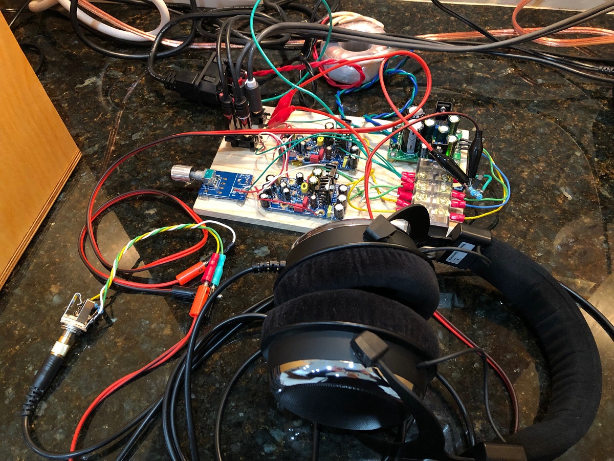
Here is 4Vpp into 240ohm load:

The modular self-contained design of the Melbourne may be easier for some folks to build as less intimidating than the whole main board on the original Aksa Lender. You can use the PSU of your choice, but a cap multiplier smoothed linear is not a bad idea.
https://www.diyaudio.com/forums/hea...-class-headphone-amp-pre-amp.html#post5626218
Here is 4Vpp into 240ohm load:
The modular self-contained design of the Melbourne may be easier for some folks to build as less intimidating than the whole main board on the original Aksa Lender. You can use the PSU of your choice, but a cap multiplier smoothed linear is not a bad idea.
If I wanted to add a second output for the subwoofer is it as simple as wiring in another outlet from the output side of the volume control? I realize this would be before the pre but I don't think the subwoofer plate amp needs the gain that the pre adds. Any impedance issues? Subwoofer has a 10k input impedance.
spiggs - it does not look like you have received an answer yet. I asked the same question a while back. See post #615 and subsequent posts.
I have simply wired up a second outlet (after the pre, ie splitting the output) for subwoofer duties later, but have not tested it with both outputs simultaneously yet.
As long as combined load of both amps in parallel is not lower than 2k you will be fine. If you need to drive lower impedance, we can boost bias current by changing 47R resistor under the CCS to say 33R or 27R. Provide more heatsinking of course.
If you notice the Melbourne can drive 520R no problem. But that’s 45mA bias current.
If you notice the Melbourne can drive 520R no problem. But that’s 45mA bias current.
spiggs - it does not look like you have received an answer yet. I asked the same question a while back. See post #615 and subsequent posts.
I have simply wired up a second outlet (after the pre, ie splitting the output) for subwoofer duties later, but have not tested it with both outputs simultaneously yet.
Thanks for the reply. So I gather if I just spilt the output into my sub and ACA, both have input at 10k yielding a 5k load, I should be fine. I should also note I am going to run some .14uf caps before the input to the ACA to roll of some low end. Any point in worrying about too much gain into the sub?As long as combined load of both amps in parallel is not lower than 2k you will be fine. If you need to drive lower impedance, we can boost bias current by changing 47R resistor under the CCS to say 33R or 27R. Provide more heatsinking of course.
If you notice the Melbourne can drive 520R no problem. But that’s 45mA bias current.
One more question. About to order the parts, if I leave out anything marked optional on the BOM will I end up with a good basic preamp or do I need to make some choices where it says optional? Is the BOM all updated in the GB thread, I tried to read through the noted items but didn't get if it was just the schematic or the BOM as well that had errors
im sorry for jumping in with the questions but this is a long thread.
can this be ran with lower voltage and much lower output/gain?
i only need gain of 3 or so, and at 18v +/- rail.
my amp's already high gain.
can this be ran with lower voltage and much lower output/gain?
i only need gain of 3 or so, and at 18v +/- rail.
my amp's already high gain.
Yes, it will work at 36v. Remember it is single rail. The new Melbourne is dual rail.
Replace R10=10k and and adjust the shunt resistor R11 to a value to give gain of 3. About 4k7 should work for gain of 3.
Replace R10=10k and and adjust the shunt resistor R11 to a value to give gain of 3. About 4k7 should work for gain of 3.
Can the Lender be setup as both a preamp and headphone amp? My headphones are the Meze 99 classics 32 ohm and really easy to drive.
Can the Lender be setup as both a preamp and headphone amp? My headphones are the Meze 99 classics 32 ohm and really easy to drive.
Yes, please see this thread:
Aksa Lender HPA
Or even several posts back in this thread I show how I am using the Melbourne to drive headphones here:
The Melbourne Class A Headphone Amp and Pre-amp
Thanks X, it does have the knob but since I m using my mini DSP volume control I kept the knob inside 😉.
great sounding preamp.
great sounding preamp.
Yes, please see this thread:
Aksa Lender HPA
Or even several posts back in this thread I show how I am using the Melbourne to drive headphones here:
The Melbourne Class A Headphone Amp and Pre-amp
Thanks. Can you recommend a source for the 2SA1837 ? Also I copied the Mouser BOM on post #671 and tried to update for the HPA version. A few items are out of stock and I would like to get a once over on the BOM. Any good available replacements? Here is my project
Mouser AKSA Lender HPA
There is a new Toshiba substitute for 2SA1837 called the TTA004B. Can handle up to 1amp, although less dissipation.
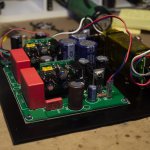
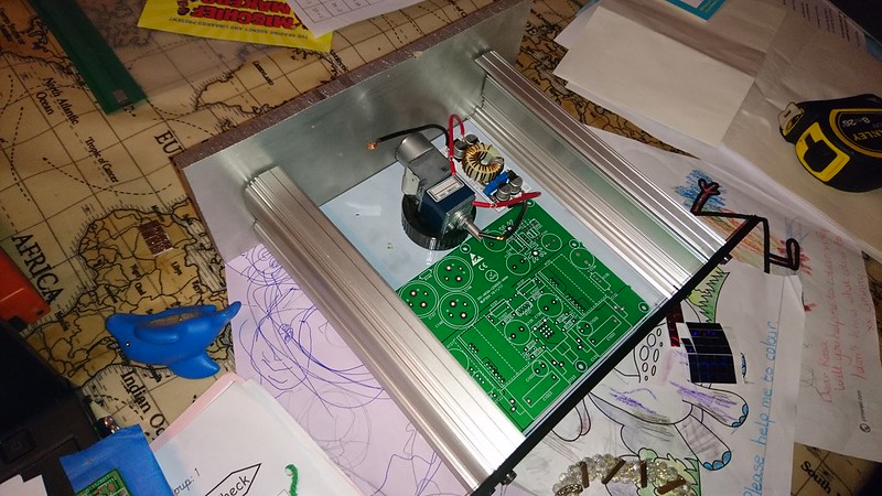
Right, I'm just starting my build here and this is my basic layout:
 DSC_0363 by billbackhouse, on Flickr
So the base of the enclosure is 3mm aluminium, the main PCB will be raised on 5mm spacers to clear, the little boost board will be mounted directly on the base, the volume control will sit approximately where it is on a folded sheet metal mount, and I intend to build a 3 way relay based source switch in the remaining void (left of the vol pot). The switch will feed the pot directly, this will then feed the main PCB and the volume control will just extend on a 6mm shaft to the front of the enclosure.
The front will be made from the 10mm aluminium plate currently at the back of the chassis, the rear of the chassis will probably be 6mm aluminium or possibly delrin (would a plastic rear panel be sensible or not?). I will drop a small form arduino in there to drive the volujme and source switching from my samsung telly remote.
Power will be 24vDC daisychained from the Pass ACA this is driving. Do i need the filter circuit supplied, or can I run the boost output at about 47v directly into the main PCB on x141 with no ill effects?
Any suggestions for a nice miniature(ish) relay for source switching I don't mind SMT or though hole.
Any thoughts or suggestions for the build?
DSC_0363 by billbackhouse, on FlickrSo the base of the enclosure is 3mm aluminium, the main PCB will be raised on 5mm spacers to clear, the little boost board will be mounted directly on the base, the volume control will sit approximately where it is on a folded sheet metal mount, and I intend to build a 3 way relay based source switch in the remaining void (left of the vol pot). The switch will feed the pot directly, this will then feed the main PCB and the volume control will just extend on a 6mm shaft to the front of the enclosure.
The front will be made from the 10mm aluminium plate currently at the back of the chassis, the rear of the chassis will probably be 6mm aluminium or possibly delrin (would a plastic rear panel be sensible or not?). I will drop a small form arduino in there to drive the volujme and source switching from my samsung telly remote.
Power will be 24vDC daisychained from the Pass ACA this is driving. Do i need the filter circuit supplied, or can I run the boost output at about 47v directly into the main PCB on x141 with no ill effects?
Any suggestions for a nice miniature(ish) relay for source switching I don't mind SMT or though hole.
Any thoughts or suggestions for the build?
You need to use a CLC filter between your ACA PSU and the DC step up. Else you may get some noise back to your ACA amp. Better to use a separate 12v 1000mA or 24v 500mA Class 2 transformer wall wart commonly seen on routers, modems etc.
- Home
- Source & Line
- Analog Line Level
- AKSA's Lender Preamp with 40Vpp Output