I ran simulations with “R11” in and out and found it is not needed from performance standpoint. Wayne Colburn’s amp doesn’t have it or the voltage reference ICs and looks a lot more symmetric. But leaving off the voltage references created a lot more distortion. This VAS is the key to the Aksa Lender front end and has been tested now in 3 different amps. I don’t think added test points needed. I tend to leave my TO92 transistors standing tall so pins are there tonhook an Oscope probe to in any event.
Stripped of the Edcor, it really reverts to being the optical isolator bias control system
Some more notes after longer term listening...
I would be interested in your opinion of the optical bias v the BA2 style TL431, so far, haven't seen any comments or comparisons; is there an audiable difference?
R11 is there to limit bias change on large current transient to a low impedance load.I ran simulations with “R11” in and out and found it is not needed from performance standpoint. ...
I ran simulations with “R11” in and out and found it is not needed from performance standpoint. Wayne Colburn’s amp doesn’t have it or the voltage reference ICs and looks a lot more symmetric. But leaving off the voltage references created a lot more distortion. This VAS is the key to the Aksa Lender front end and has been tested now in 3 different amps. I don’t think added test points needed. I tend to leave my TO92 transistors standing tall so pins are there tonhook an Oscope probe to in any event.
As long as you are certain you've made no obvious mistakes, please by all means proceed and follow your instincts. I very gently recommend you set aside time and money to manufacture a few complete & total do-overs of the PCB layout, along with a few replace-all-parts rebuilds. Maybe, in the fullness of time, you won't require these. But it could possibly turn out to be a very shrewd play: prepare in advance. In effect, to buy insurance.
Are you kidding? I have enough parts on hand to build maybe three more variants of the Alpha 20/BB/M2 (and almost any other amp as long as unobtanium is not involved). I have learned that first board runs of new design should be minimum number in case a mistake is made. This was the case on Alpha BB.
With Mark Johnson's blessings, JPS64 and I are also working on a small Aksa Lender DB that will go on the M2X amp as drop in replacement DB. Given that the Aksa Lender was designed by Hugh Dean, we are calling the new DBs "The Melbourne".
https://www.diyaudio.com/forums/pass-labs/321925-diyaudio-watt-m2x-93.html#post5608516
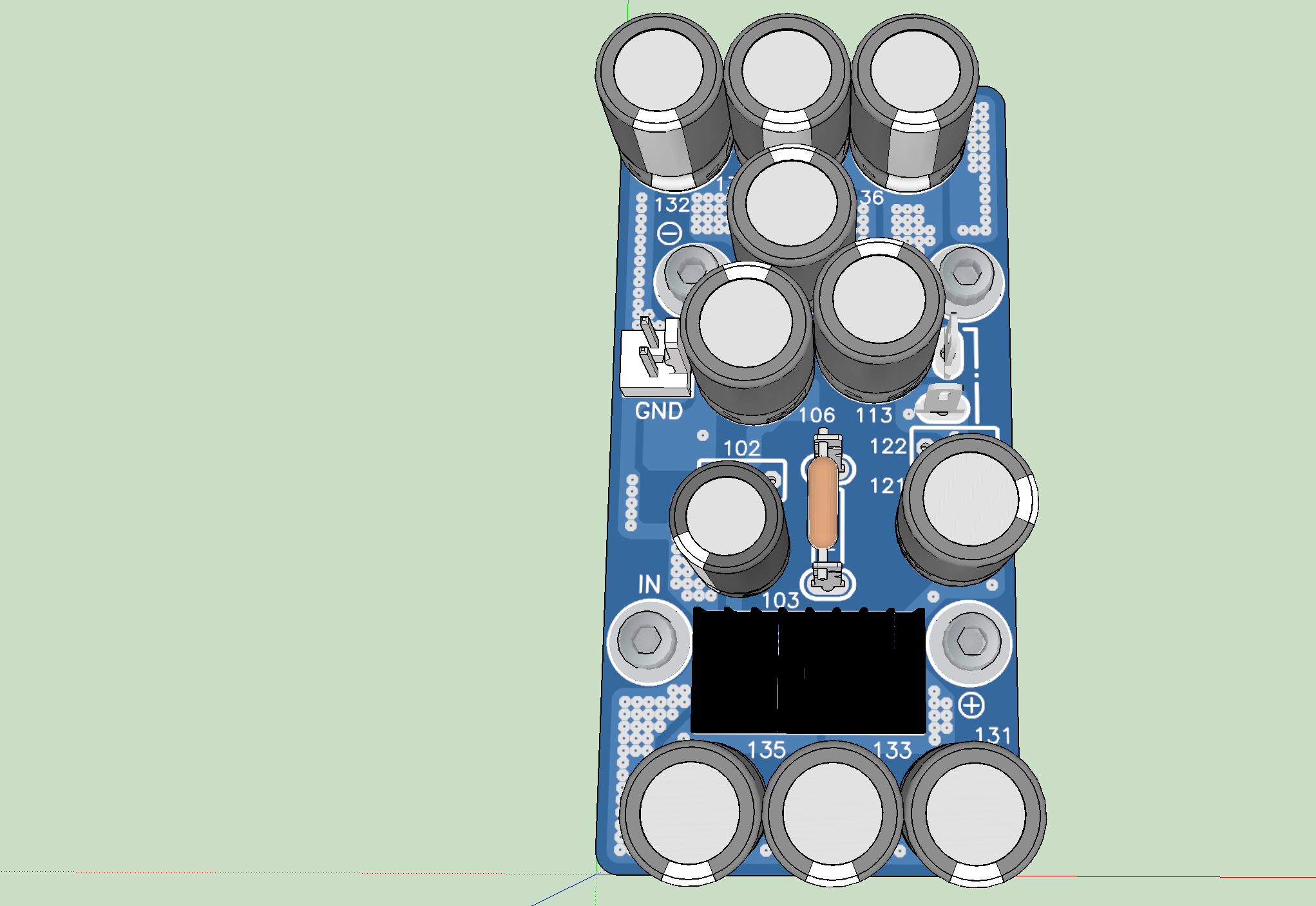
Some initial renders of the TH variant, an SMT one will probably be made as well. I suspect a mezzanine CRCRC board will also be needed.
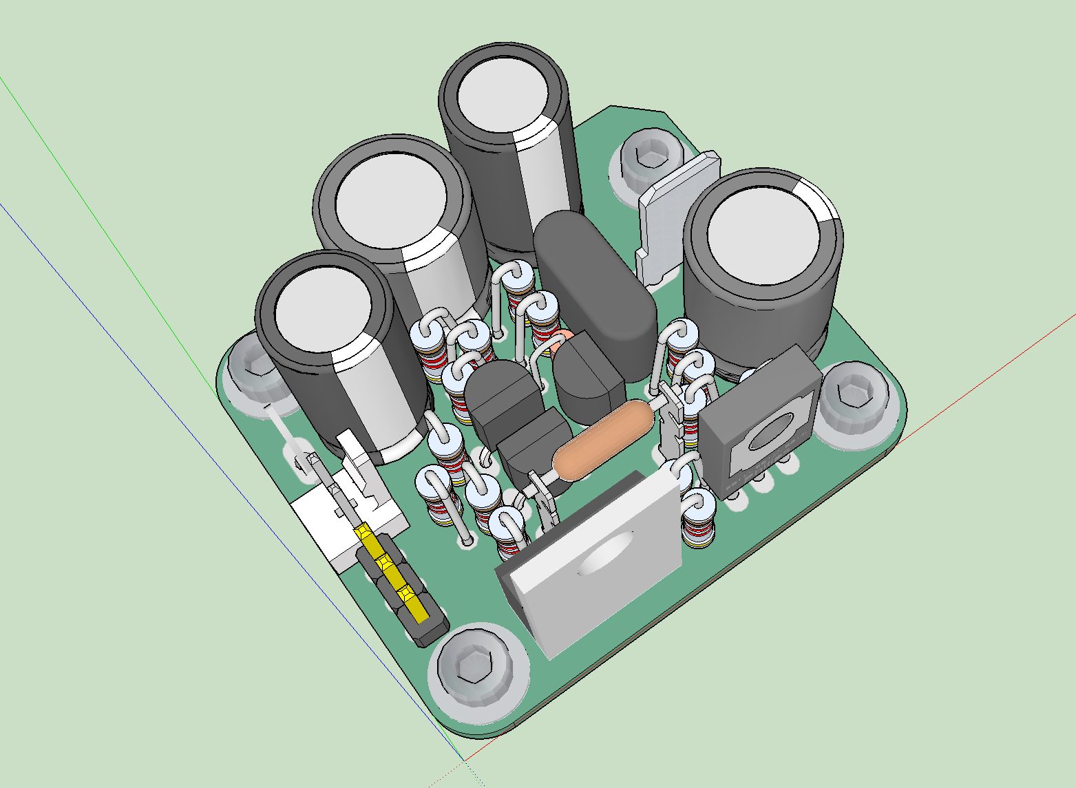
Performance is predicted to be very good and it has 0mV DC offset and can be DC coupled.
Here is predicted FFT for 4Vpp (label says 2vpp is incorrect) into the Edcor load, which should yield about 8.5wrms at the speakers (this is FFT from input stage to a 6k load - not power amp output):

https://www.diyaudio.com/forums/pass-labs/321925-diyaudio-watt-m2x-93.html#post5608516
Some initial renders of the TH variant, an SMT one will probably be made as well. I suspect a mezzanine CRCRC board will also be needed.
Performance is predicted to be very good and it has 0mV DC offset and can be DC coupled.
Here is predicted FFT for 4Vpp (label says 2vpp is incorrect) into the Edcor load, which should yield about 8.5wrms at the speakers (this is FFT from input stage to a 6k load - not power amp output):
Last edited:
Hi Mark,
I missed that thread - thanks for the link. Ok, so I already looked into the worst case of 600ohm load so we need to boost bias current a bit. The Aksa Lender can drive 32ohm headphones when configured with 100ma bias current.
Re-ran sims with 600ohm load and here is what I get for 4Vpp - same bias current as before (no changes to circuit). 4Vpp with Edcor 6x gain is about 8.5wrms:
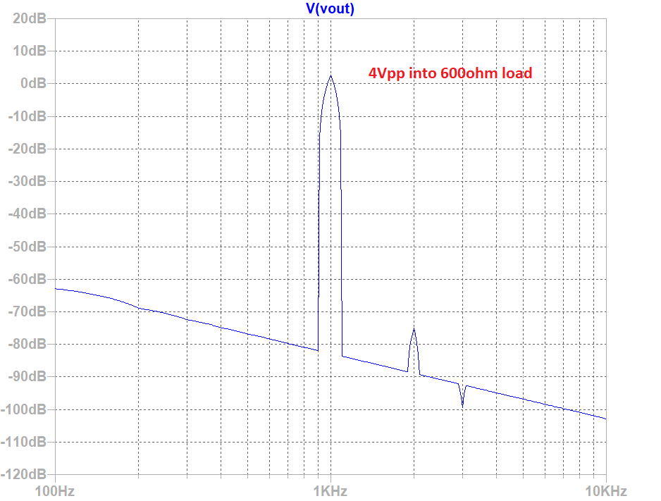
Predicted distortion components here with THD about 0.014%, still great looking profile:
I missed that thread - thanks for the link. Ok, so I already looked into the worst case of 600ohm load so we need to boost bias current a bit. The Aksa Lender can drive 32ohm headphones when configured with 100ma bias current.
Re-ran sims with 600ohm load and here is what I get for 4Vpp - same bias current as before (no changes to circuit). 4Vpp with Edcor 6x gain is about 8.5wrms:
Predicted distortion components here with THD about 0.014%, still great looking profile:
Code:
Harmonic	Frequency	 Fourier 	Normalized	 Phase  	Normalized
 Number 	  [Hz]   	Component	 Component	[degree]	Phase [deg]
    1   	1.000e+03	1.913e+00	1.000e+00	    0.13°	    0.00°
    2   	2.000e+03	2.494e-04	1.304e-04	  102.02°	  101.88°
    3   	3.000e+03	1.402e-05	7.328e-06	  179.41°	  179.28°
    4   	4.000e+03	2.448e-05	1.279e-05	 -176.41°	 -176.55°
    5   	5.000e+03	1.969e-05	1.029e-05	 -179.93°	 -180.06°
    6   	6.000e+03	1.630e-05	8.519e-06	 -179.98°	 -180.12°
    7   	7.000e+03	1.397e-05	7.301e-06	 -179.95°	 -180.09°
    8   	8.000e+03	1.222e-05	6.389e-06	 -179.96°	 -180.09°
    9   	9.000e+03	1.086e-05	5.679e-06	 -179.96°	 -180.10°
   10   	1.000e+04	9.778e-06	5.111e-06	 -179.97°	 -180.10°
   11   	1.100e+04	8.889e-06	4.647e-06	 -179.97°	 -180.10°
   12   	1.200e+04	8.149e-06	4.259e-06	 -179.97°	 -180.11°
   13   	1.300e+04	7.522e-06	3.932e-06	 -179.97°	 -180.11°
   14   	1.400e+04	6.985e-06	3.651e-06	 -179.98°	 -180.11°
   15   	1.500e+04	6.519e-06	3.408e-06	 -179.98°	 -180.11°
Total Harmonic Distortion: 0.013278%(0.053681%)
Attachments
Last edited:
JPS64 and I are in the designing the layout to be compliant with M2X and still fit into a case and be UMS compliant as well. We may have to go beyond the original DB’s 40mm x 35mm outline in order to fit a much needed CRCRC power rail filter for the input stage as it will be DIR en directly from relatively noisy rails. Something like this:
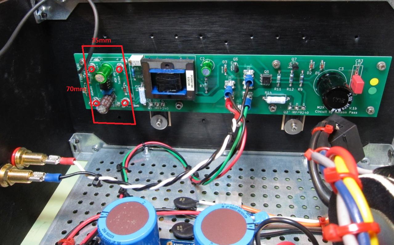
If you have comments or suggestions on how to extend board, let us know.
If you have comments or suggestions on how to extend board, let us know.
JPS64 and I are in the designing the layout to be compliant with M2X and still fit into a case and be UMS compliant as well. We may have to go beyond the original DB’s 40mm x 35mm outline in order to fit a much needed CRCRC power rail filter for the input stage as it will be DIR en directly from relatively noisy rails. Something like this:
If you have comments or suggestions on how to extend board, let us know.
On the end, you still keep the transformer on the PC boards, the reason I ask because of a few designs like that already exist even at the DIY audio store plus ZM did something similar. Or you just illustrating the first modification later the transformer will be removed. 🙂
Hi Gaborbela,
This is a separate project actually - just an easy to use daughterboard for those who have the Mark Johnson M2X amp already. They have the choice of using the Edcor or bypassing it.
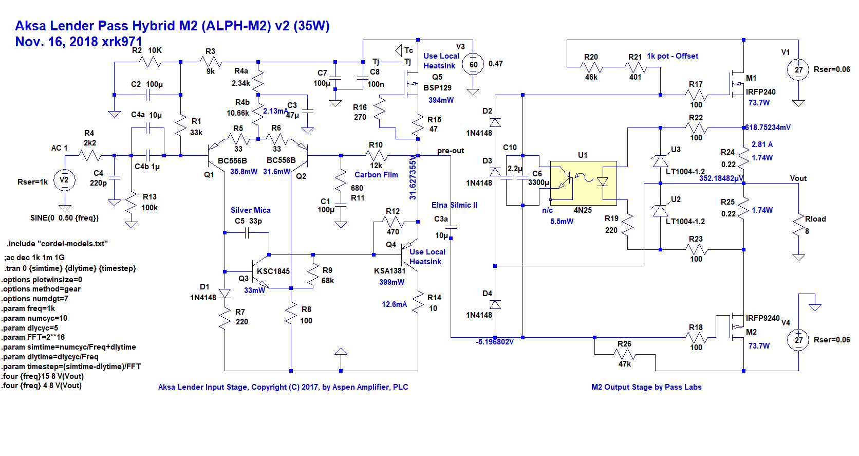
The ALPH-M2X will be a new amp with integrated Aksa Lender front end and negative feedback loop with the opto-isolator controlled push-pull output stage located where the depletion mode CCS mosfet would have been and a PMOS locates where the PNP BJT would have been.
This is a separate project actually - just an easy to use daughterboard for those who have the Mark Johnson M2X amp already. They have the choice of using the Edcor or bypassing it.
The ALPH-M2X will be a new amp with integrated Aksa Lender front end and negative feedback loop with the opto-isolator controlled push-pull output stage located where the depletion mode CCS mosfet would have been and a PMOS locates where the PNP BJT would have been.
Here is a 35w variant with +/-27v rails and 2.81A bias current:
Here is predicted FFT for 8wrms into 8ohms, looks much better now:
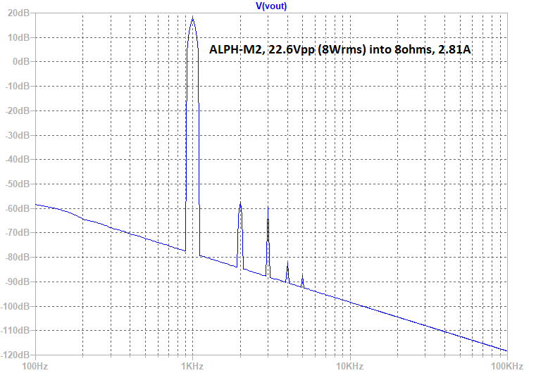
Here are predicted distortion components and THD is about 0.02% but dominant H2 and lower H3, 8wrms into 8ohms:
For 1W into 8ohms is is now 0.005%THD
Following along here and on the Pass Labs forum. Interesting, I intend to try the proposed daughter board for M2x.
The 35 watt is quite the departure, (not that there is anything wrong with that) especially with the H2 dominant with lower H3...The original M2 being a H3 dominant amp, which surprised me when I learned that.
Will the proposed daughter card effect this H2 dominant situation, or must the entire 35 watt variation be required? Comparing more H2 to original M2 sounds interesting.
While an even farther departure from original M2, the notion of trying sans transformer, combined with H2 dominance is also interesting, which with jumpers, appears from your writing to be possible with proposed daughter cards.
All this with still keeping the neato opto bias arrangement is very interesting.
Standing by, and waiting for answer regarding increased H2 being possible with M2x daughter card, or if entire 35 watt version required....I fear another amp build coming, several unfinished as is. Situation normal...
Russellc
Hi Russellc,
The M2X can have dominant H2 possibly with just the Melbourne DB. I don’t know since I haven’t tried to drive it with the Edcor in place. Certainly, if you bypass the Edcor, it will be H2 dominant as it follows what the input stage gives it for the most part.
My M2 (Teabag) was actually H2 dominant but just had a lot of higher order harmonics as well, and the THD was up in the 0.3% level at 1W.
You can either remove the Edcor by desoldering (not an easy task given number of eaters large pins all securely soldered in place). Or cut the trace from the Edcor to C2 and from the DB to the Edcor. Then jumper the output of the DB (pin 4) to C2. The cut traces can be restored with a bead of solder over the scraped off solder mask. It won’t look like a pristine board anymore but won’t impact performance. You could even wire a DPST toggle switch to allow flipping back and forth with and without. Although without is 6x less gain.
Last edited:
Hi Russellc,
The M2X can have dominant H2 possibly with just the Melbourne DB. I don’t know since I haven’t tried to drive it with the Edcor in place. Certainly, if you bypass the Edcor, it will be H2 dominant as it follows what the input stage gives it for the most part.
My M2 (Teabag) was actually H2 dominant but just had a lot of higher order harmonics as well, and the THD was up in the 0.3% level at 1W.
You can either remove the Edcor by desoldering (not an easy task given number of eaters large pins all securely soldered in place). Or cut the trace from the Edcor to C2 and from the DB to the Edcor. Then jumper the output of the DB (pin 4) to C2. The cut traces can be restored with a bead of solder over the scraped off solder mask. It won’t look like a pristine board anymore but won’t impact performance. You could even wire a DPST toggle switch to allow flipping back and forth with and without. Although without is 6x less gain.
Thanks, I will stand back and wait. My M2 is also Teabag kit, dont want to slice and dice it. I have Mark's board set and will use them once the smoke clears.
Thanks again,
Russellc
The SMT version is coming along, and you can see JPS64's artistry here. We are getting closer but still working out a few issues with keeping the cap sizes as small as possible by using close to actual working voltages needed rather than over-specifying them. The topside of the outputs are getting a small stick-on heatsink to help dissipate some of that Class A heat (circa 750mW).
Here are latest renders.
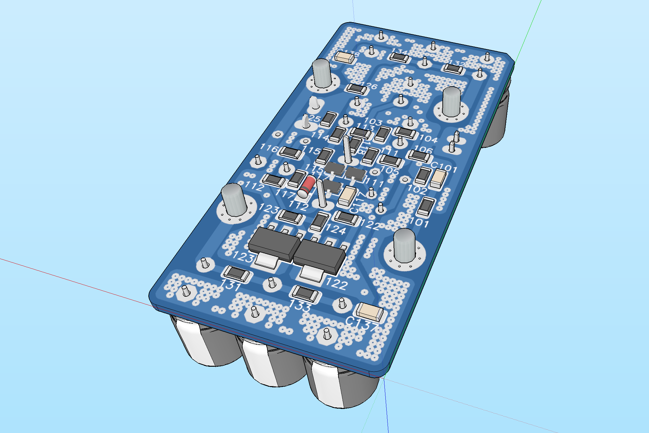
Here are latest renders.
Attachments


- Status
- Not open for further replies.
- Home
- Amplifiers
- Solid State
- AKSA Lender Pass Hybrid M2 (ALPH-M2) Amp