Hi Indra,
Thanks - please repost your image of schematic as its not pulling up on my browser. Maybe post image directly to DIYA server.
X
Thanks - please repost your image of schematic as its not pulling up on my browser. Maybe post image directly to DIYA server.
X
PNP Emitter follower "Q4" from post #1, has been removed. Now the collector of VAS transistor Q3, directly drives the Gate-Drain capacitances of the output MOSFETs M1 and M2, introducing additional phase lag at HF. VAS collector load is now 7.5K, down from 68K in post #1, so LF gain is reduced. Quad power supplies (!!), 28V and 23V, become duals if you increase the heatsink and run the output stage from 28V rails. New resistor R6 across the 4N35's phototransistor, reduces the optical bias loop's gain at DC.
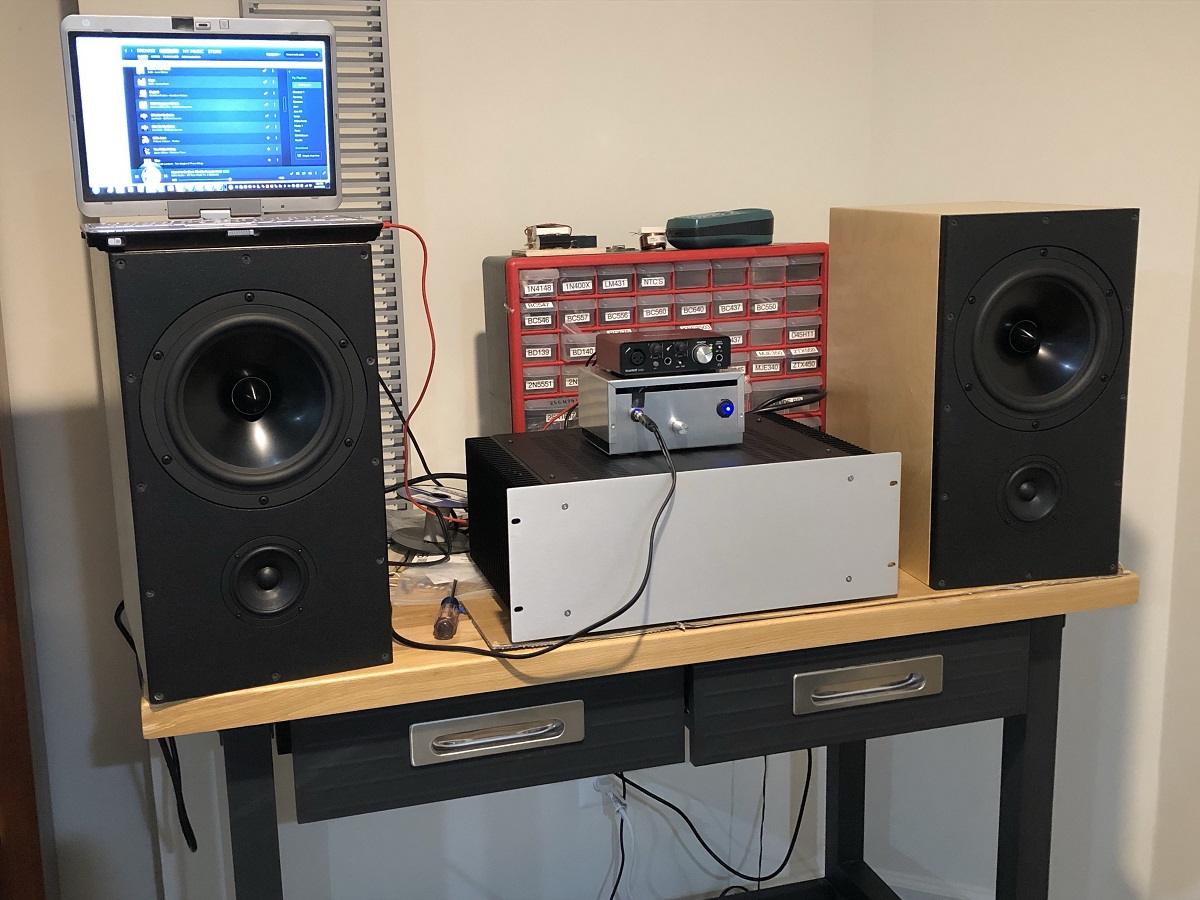
Some more notes after longer term listening with my reference 10F/RS225 FAST speakers. The ALPH-M2 sounds very good. Dynamics and clarity are excellent. Reminiscent of an Alpha 20 but with the sweetness turned up a bit. Bass authority is excellent and soundstage and imaging are superb. Overall presentation is very natural, relaxed, but still very engaging. Blacks are very black and dynamic range seems increased. Compared to an Edcor M2, I feel that a veil of noise has been lifted. Overall a much more enjoyable amp for me. I really enjoy being able to turn up the volume to foot-tapping levels without the feel of congestion. The sound is just very open and spacious. Nice amp - a keeper for sure.
Attachments

Thank you for the nice remark Hugh.
And thank you Mark. For integrated Lender FE into an M2 OS, a dual 24V supply will do 20W while a dual 23V for the OS and a dual 28V for the FE will be good for up to about 25W. Since the dual 28V is low power, it is easier to justify adding better filter and regulation. Adding another follower stage can address remaining issues while retaining M2 style opto bias, but then it is no longer an M2 OS. 🙂
And thank you Mark. For integrated Lender FE into an M2 OS, a dual 24V supply will do 20W while a dual 23V for the OS and a dual 28V for the FE will be good for up to about 25W. Since the dual 28V is low power, it is easier to justify adding better filter and regulation. Adding another follower stage can address remaining issues while retaining M2 style opto bias, but then it is no longer an M2 OS. 🙂
Attachments
Last edited:

That’s very compact, JPS64! Have you tried the experiment simply by connecting the Aksa Lender Preamp to an Edcor-bypassed M2?
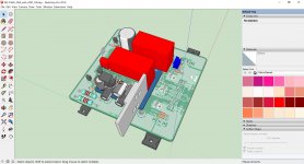
It´s really bad, I´ve loaned out to friends my two M2 amplifier!
I´ve to build next one, only 3U case missing (as for ALPHA 20).
JP
I´ve to build next one, only 3U case missing (as for ALPHA 20).
JP
Am I correct in thinking that this hybrid is in effect an integrated amp? Surely, there won't be a need for an additional preamp.
Yes, it will be integrated and have decent gain circa 26dB to 30dB (or lower if you choose). The Aksa Lender front end provides an effective method to get gain with low distortion and the M2 output stage provides the power. I am debating whether or not it makes sense to make a dual rail Aksa Lender front end (as was done on Alpha 20) and then integrate with the Pass optical isolator amplifier bias system. It’s not an M2 per se as the DNA of the M2 was the Edcor. Stripped of the Edcor, it really reverts to being the optical isolator bias control system given in Pass’ patent from 1988:
https://www.passlabs.com/sites/default/files/pat_4752.jpg
You can take this output stage and pair it with ANY front end. I just happen to think the Aksa Lender is one of the nicest sounding ones, and capable of easily driving the output to clipping at 40Vpp - or higher as would be needed for a 35w amp.
You can take this output stage and pair it with ANY front end. I just happen to think the Aksa Lender is one of the nicest sounding ones...
I have to agree with you X. The AKSA Lender pre really sounds superb.

And this hybrid combo amp is going to be hard to beat. I foresee a lot of builds in the future. Without unobtanium components or autoformer, the output stage is an easy build.
In case you haven't figured it out yet, I have become a huge fan of yours - and with good reason.

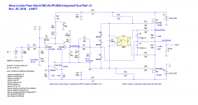
ALPH-M2 Dual Rail v3
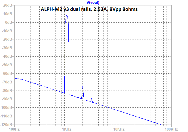
Here is my first cut at a dual rail version based on Alpha 20 front end and driving the M2 output with a low level of negative feedback similar to the Alpha 20. The performance with regards to reduction in THD is substantial as you might expect, and the harmonic profile continues to remain as H2 dominant with a reduced level of H3. At 8Vpp into 8ohms (1wrms) the THD is in the 0.006% range now, and at 8wrms, it is about 0.02%.
Here is the schematic, note that the parts count has gone down by 2 actives now that the front end is integrated:

Here is predicted FFT for 8vpp (1wrms):
Here are the predicted distortion components for 8Vpp:
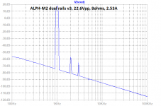
Here is predicted FFT for 8vpp (8wrms):

Here are the predicted distortion components for 22.6Vpp:
So this looks like it could be implemented as a small modification to the original Alpha 20 PCB board format which would make it UMS compliant. Of note with this system is that there is NFB and there is no way not to have it. The Aksa Lender pre needs to have some output drivers to work, and disconnecting the feedback loop here breaks the circuit. But perhaps Hugh can chime in if he knows of a way we can have this system work with a solder pad jumper that turns on/off NFB.
Here is my first cut at a dual rail version based on Alpha 20 front end and driving the M2 output with a low level of negative feedback similar to the Alpha 20. The performance with regards to reduction in THD is substantial as you might expect, and the harmonic profile continues to remain as H2 dominant with a reduced level of H3. At 8Vpp into 8ohms (1wrms) the THD is in the 0.006% range now, and at 8wrms, it is about 0.02%.
Here is the schematic, note that the parts count has gone down by 2 actives now that the front end is integrated:
Here is predicted FFT for 8vpp (1wrms):
Here are the predicted distortion components for 8Vpp:
Code:
8.14Vpp, into 8ohms, 2.53A v3 dual rail
Harmonic	Frequency	 Fourier 	Normalized	 Phase  	Normalized
 Number 	  [Hz]   	Component	 Component	[degree]	Phase [deg]
    1   	1.000e+03	4.078e+00	1.000e+00	  179.21°	    0.00°
    2   	2.000e+03	2.573e-04	6.308e-05	   94.83°	  -84.37°
    3   	3.000e+03	4.545e-05	1.114e-05	 -173.56°	 -352.77°
    4   	4.000e+03	1.142e-05	2.799e-06	 -178.68°	 -357.88°
    5   	5.000e+03	9.045e-06	2.218e-06	 -179.42°	 -358.63°
    6   	6.000e+03	7.582e-06	1.859e-06	 -179.29°	 -358.49°
    7   	7.000e+03	6.500e-06	1.594e-06	 -179.39°	 -358.60°
    8   	8.000e+03	5.687e-06	1.395e-06	 -179.47°	 -358.67°
    9   	9.000e+03	5.056e-06	1.240e-06	 -179.53°	 -358.73°
   10   	1.000e+04	4.550e-06	1.116e-06	 -179.57°	 -358.78°
   11   	1.100e+04	4.136e-06	1.014e-06	 -179.61°	 -358.82°
   12   	1.200e+04	3.791e-06	9.297e-07	 -179.66°	 -358.87°
   13   	1.300e+04	3.500e-06	8.583e-07	 -179.67°	 -358.88°
   14   	1.400e+04	3.250e-06	7.970e-07	 -179.70°	 -358.91°
   15   	1.500e+04	3.034e-06	7.439e-07	 -179.72°	 -358.93°
Total Harmonic Distortion: 0.006427%(0.012307%)
Here is predicted FFT for 8vpp (8wrms):
Here are the predicted distortion components for 22.6Vpp:
Code:
22.6Vpp, into 8ohms, 2.53A v3 dual rail
Harmonic	Frequency	 Fourier 	Normalized	 Phase  	Normalized
 Number 	  [Hz]   	Component	 Component	[degree]	Phase [deg]
    1   	1.000e+03	1.133e+01	1.000e+00	  179.21°	    0.00°
    2   	2.000e+03	1.994e-03	1.761e-04	   91.42°	  -87.79°
    3   	3.000e+03	7.361e-04	6.499e-05	 -170.16°	 -349.36°
    4   	4.000e+03	3.533e-05	3.119e-06	 -175.92°	 -355.13°
    5   	5.000e+03	1.813e-05	1.601e-06	  146.91°	  -32.29°
    6   	6.000e+03	2.081e-05	1.838e-06	 -178.42°	 -357.63°
    7   	7.000e+03	1.848e-05	1.632e-06	 -176.61°	 -355.81°
    8   	8.000e+03	1.592e-05	1.405e-06	 -179.53°	 -358.74°
    9   	9.000e+03	1.410e-05	1.245e-06	 -179.86°	 -359.06°
   10   	1.000e+04	1.270e-05	1.121e-06	 -179.57°	 -358.78°
   11   	1.100e+04	1.155e-05	1.020e-06	 -179.58°	 -358.79°
   12   	1.200e+04	1.059e-05	9.348e-07	 -179.65°	 -358.86°
   13   	1.300e+04	9.773e-06	8.629e-07	 -179.68°	 -358.89°
   14   	1.400e+04	9.075e-06	8.012e-07	 -179.70°	 -358.91°
   15   	1.500e+04	8.471e-06	7.479e-07	 -179.72°	 -358.92°
Total Harmonic Distortion: 0.018775%(0.021535%)
So this looks like it could be implemented as a small modification to the original Alpha 20 PCB board format which would make it UMS compliant. Of note with this system is that there is NFB and there is no way not to have it. The Aksa Lender pre needs to have some output drivers to work, and disconnecting the feedback loop here breaks the circuit. But perhaps Hugh can chime in if he knows of a way we can have this system work with a solder pad jumper that turns on/off NFB.
Attachments

Last edited:

Of course, similar to the Wayne Colburn HPA, but with Aksa Lender front end instead of an op amp, one can put IRF610/9610 for the outputs, drop rails to +/-18v, and change source resistors to 4R7 for 120mA bias and drive a 32R headphones very nicely. Here is headphone circuit:
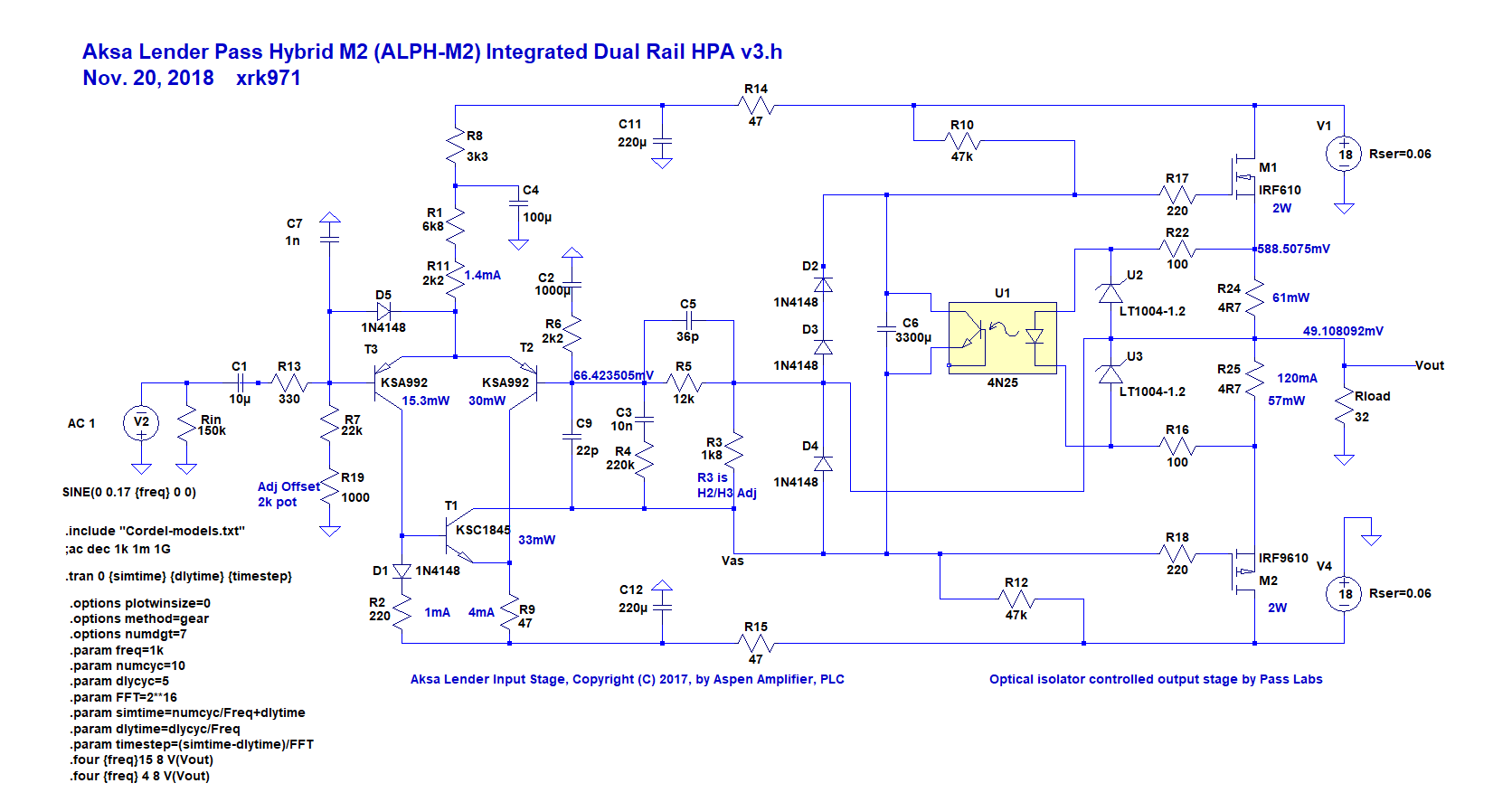
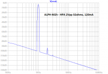
For 2vpp into 32ohms, 120mA bias, 16dB gain, predicted FFT:

Predicted distortion components for THD of about 0.003%:
For 2vpp into 32ohms, 120mA bias, 16dB gain, predicted FFT:
Predicted distortion components for THD of about 0.003%:
Code:
Harmonic	Frequency	 Fourier 	Normalized	 Phase  	Normalized
 Number 	  [Hz]   	Component	 Component	[degree]	Phase [deg]
    1   	1.000e+03	1.023e+00	1.000e+00	  179.52°	    0.00°
    2   	2.000e+03	2.937e-05	2.871e-05	   95.79°	  -83.73°
    3   	3.000e+03	3.338e-06	3.263e-06	 -178.28°	 -357.80°
    4   	4.000e+03	1.447e-06	1.415e-06	 -178.57°	 -358.09°
    5   	5.000e+03	1.156e-06	1.130e-06	 -179.08°	 -358.60°
    6   	6.000e+03	9.654e-07	9.438e-07	 -179.25°	 -358.77°
    7   	7.000e+03	8.266e-07	8.082e-07	 -179.34°	 -358.86°
    8   	8.000e+03	7.240e-07	7.079e-07	 -179.43°	 -358.95°
    9   	9.000e+03	6.431e-07	6.288e-07	 -179.49°	 -359.00°
   10   	1.000e+04	5.792e-07	5.663e-07	 -179.55°	 -359.07°
   11   	1.100e+04	5.265e-07	5.148e-07	 -179.57°	 -359.09°
   12   	1.200e+04	4.827e-07	4.719e-07	 -179.64°	 -359.16°
   13   	1.300e+04	4.456e-07	4.356e-07	 -179.64°	 -359.16°
   14   	1.400e+04	4.138e-07	4.046e-07	 -179.68°	 -359.20°
   15   	1.500e+04	3.860e-07	3.774e-07	 -179.69°	 -359.21°
Total Harmonic Distortion: 0.002902%(0.006056%)
Attachments
Last edited:
I suspect you may want to ask Pass Labs circuit experts whether it's a wise idea or a bad idea to delete the resistor named "R11" in the Official M2 Schematic (link) . NP might have put it in the design for a very good reason.
I also think the collector bias scheme for your "VAS" transistor is quite original and unorthodox. I recommend including Test Points on the PCB layout around that node, to make it easy to connect a scope probe and leave it there without holding it by hand. So you can view the collector and (some other node) simultaneously, on a dual trace scope, while having both hands free to twirl the knobs and adjust the scope, the signal generator, etc.
Same goes for adjusting output offset voltage by changing resistance-to-ground at the noninverting input. May want to make it very easy to probe those nodes hands-free.
- Status
- Not open for further replies.
- Home
- Amplifiers
- Solid State
- AKSA Lender Pass Hybrid M2 (ALPH-M2) Amp