Could you send aksa a pcb so aksa can show a builded version as he has decades of expirence of amp building . A real world expirence for aksa vs simulation would increse comfort among novice and beginner builders imo.
Not so fast, Tonza!
X is the man building and testing these amps and my limited energies are spent on my amp company, Aspen where I build and sell various complete AB amps.
If you are not happy with the development procedure, just wait for a week and all will be clear to you.
These amps are intermediate level. I do not suggest beginners start an ALPHA but it is the journey as much as the finishing!
HD
Tonza75,
As far as 25w-category Class A amps go, the Alpha 20 is on the easy side of the spectrum - an easy build and simple to operate as there are no adjustments. Some Class A amps have 4 pots that have to be synchronously adjusted (with two DVM's simultaneously connected and monitored) to achieve both correct bias current and DC offset. And this has to be done for different temperatures (lid on, lid off, startup vs steady state, etc). The Alpha tracks both bias current (via Aleph CCS) and DC offset with temp via matched LTPs and Aksa Lender front end. As evidenced by multiple builds here, the startup sequence has all been uneventful, and no adjustments needed.
If you would like more detailed photos and step by step instructions on populating the board, please take a look at one of 6L6's many build-guides for Pass Aleph J, F5, etc. Amps are all stuffed and soldered the same way: start with small low profile parts (resistors, diodes), then small caps, then signal transistors & pots, then large caps, then large actives, then hardware for mounting.
Last edited:
I have read your struggles with 6L6 you used pots 6L6 used jumpers your jfet where fake and babelfish and so on again. Well.Tonza75,
As far as 25w-category Class A amps go, the Alpha 20 is on the easy side of the spectrum - an easy build and simple to operate as there are no adjustments. Some Class A amps have 4 pots that have to be synchronously adjusted (with two DVM's simultaneously connected and monitored) to achieve both correct bias current and DC offset. And this has to be done for different temperatures (lid on, lid off, startup vs steady state, etc). The Alpha tracks both bias current (via Aleph CCS) and DC offset with temp via matched LTPs and Aksa Lender front end. As evidenced by multiple builds here, the startup sequence has all been uneventful, and no adjustments needed.
If you would like more detailed photos and step by step instructions on populating the board, please take a look at one of 6L6's many build-guides for Pass Aleph J, F5, etc. Amps are all stuffed and soldered the same way: start with small low profile parts (resistors, diodes), then small caps, then signal transistors & pots, then large caps, then large actives, then hardware for mounting.
Differing ac and dc gains will exbibit low frequency shift on the output under tone-burst testing.
As the is some odd exursion on loudspeaker cone seen by some Could you use an unequal mark-space ratio square wave to see is threre any DClevel-shift.
I have amended the figures to reflect 12.5W into 4R load (1.7Vpk input and 20Vpk output) and give more insight to the profile of the harmonics.
As mentioned, with loading this amplifier tends to make more H3, but even at 12.5W H3 is -88dB lower than H2 -80dB and a very good H5 output of -111dB. I believe the 8R version will sound better but this low loading for ribbon speakers should sound very good too.
The difference in FFT between the 8R and 4R version is minimal, less then 2db H3, very well done Hugh !
Here are both FFTs:
Attachments
Last edited:
Hi Hugh,
Changing the fb resistor of the ccs from 865r to 750r gives 3db lower H2 and 2db lower H3 in the Alpha20 4R version.
Good idea ?
Regards,
Danny
Changing the fb resistor of the ccs from 865r to 750r gives 3db lower H2 and 2db lower H3 in the Alpha20 4R version.
Good idea ?
Regards,
Danny
Hello,
I've now been simulating the different options of biasing the output stage and trying to minimize it a little without augmenting distortion.
So that I can use it with my 4U (hifi2000) heatsinks.
I already changed the ccs fb resistor to 750r (see previous post),
now I changed the sensor resistor of the ccs from 0.12 to 0.18 and the source resistor to 0.33 (1/3).
Strangely enough this gave me lower distortion than 0.12 with 0.81/3
with 20vpk I have now:
H2 at -86.7db
H3 at -94.3db
I'm not complaining 🙂
Hugh, I've changed your simulation with these values:
Attachments
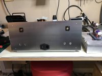
Got most of the rear panel done on the permanent case for my 20w Alpha. Working on heatsink mounting/support as they're pretty heavy.
I will likely sand then put a satin clear coat on the rear panel to keep finger prints, etc. at bay.
I will likely sand then put a satin clear coat on the rear panel to keep finger prints, etc. at bay.
Attachments
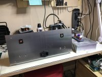
That looks real nice Pcgab! Case from scratch, or so it would appear.
Thanks!
Yep, the rear plate is ~3mm aluminum. Not sure what I'll use for the front, might get a ~6mm sheet of black Delrin for the front panel.
Working on an internal frame to support the heatsinks and top/bottom panels as well.
Hello,
I've now been simulating the different options of biasing the output stage and trying to minimize it a little without augmenting distortion.
So that I can use it with my 4U (hifi2000) heatsinks.
I already changed the ccs fb resistor to 750r (see previous post),
now I changed the sensor resistor of the ccs from 0.12 to 0.18 and the source resistor to 0.33 (1/3).
Strangely enough this gave me lower distortion than 0.12 with 0.81/3
with 20vpk I have now:
H2 at -86.7db
H3 at -94.3db
I'm not complaining 🙂
Hugh, I've changed your simulation with these values:
Danny,
Can’t wait to hear what your impressions are.
I’m running 8ohm 89db speakers, so not sure how well it will work with them.
With 8ohm speakers there's no need for the Alpha 4R,
better build the Alpha20 8R.
As for a 8R lower gain version, that depends of how much gain you need in your system: Vout of sources, preamp, speakers sensitivity, how loud you play.
This test: How much Voltage (power) do your speakers need, can tell you something about your speakers.
Regards,
Danny
better build the Alpha20 8R.
As for a 8R lower gain version, that depends of how much gain you need in your system: Vout of sources, preamp, speakers sensitivity, how loud you play.
This test: How much Voltage (power) do your speakers need, can tell you something about your speakers.
Regards,
Danny
Last edited:
Hi Tonza,
I read but could only understand this partly. 😕 I'm not too good on the technical words, but you need not be concerned about this amplifier. I believe you are concerned about DC offset on the speaker, not a trivial issue but well handled with a long tailed pair including a quasi-current mirror in the output. You may be talking about mark-space square wave test to assess if DC offset appears with asymmetric signals, but not musical signal. The answer is no, this will not an issue, particularly as the time constant of the 220uF/865R is below 2Hz and would be knocked out by most sources. I believe most amps will cause issues with asymmetric signals however, but it is largely an academic phenomenon, obviated with a DC protection system for the speaker. I would also say that if you are worried about these sophisticated problems in audio you might read more about it; it's not a big issue in small power amplifiers but important on large PA systems. Most large amps use DC sense circuit which disconnect the amp from the speaker if more than a couple of volts DC appears across the voice coil but in this low power amp with 24V rails aiming for stratospheric sound quality it will never be an issue.
Danny,
I would urge you to leave the original settings; 0.12R for the AC CCS sense, 0.81R triples (giving a combined 0.27R current sense for a single IXYS 480W device) and 865R AC CCS sense resistor.
Attached is a simulation of what happens with your settings (0.18R, 1R triplet, 750R) at 35Vpp output into 4R. There is high distortion, too and THD is over 1% at high power because one of the outputs turns off. You can see the current curves of the two outputs, they are not equal in range, and the bottom device turns off completely. It will be OK at 32Vpp output, but we need to correct each device current flow so they have identical range from low to high current with neither device turning off, like my second attachment.
As you increase the current source from 0.81 to 1R and beyond you reduce the limit of current from the upper device near clip. You need the highest figure you can attain to maximum power output, and higher resistors here also bring down the clip level.
By increasing the CCS sense current from 0.12R you increase the output impedance, reducing the damping factor with 4R speakers. This is critical for 4R. You are also throwing signal away with a higher value; 0.12R is about as low as you can do it.
Finally, the CCS base driver resistor, 865R, is CRITICAL on this amp. It sets the dynamic current variation of the output devices so that they go up and down AND down and up IDENTICALLY. The current dynamic of each output device should be equal; as one goes from 80mA up to 1.6A the other device must come down from 1.6A to 80mA - a perfect 'see-saw' match. Only this delivers maximum power to the load at the highest efficiency and with neither output device turning off at any stage. This is very important and is the hallmark of Nelson's brilliant design. I cannot stress how clever this circuit block is to audio amplifiers; it doubles the efficiency of a single ended amplifier whilst delivering inexpensive push pull topology, yet delivering a wonderful sound quality by ensuring now output device ever turns off.
Hugh
Differing ac and dc gains will exbibit low frequency shift on the output under tone-burst testing.
As the is some odd exursion on loudspeaker cone seen by some Could you use an unequal mark-space ratio square wave to see is threre any DClevel-shift.
I read but could only understand this partly. 😕 I'm not too good on the technical words, but you need not be concerned about this amplifier. I believe you are concerned about DC offset on the speaker, not a trivial issue but well handled with a long tailed pair including a quasi-current mirror in the output. You may be talking about mark-space square wave test to assess if DC offset appears with asymmetric signals, but not musical signal. The answer is no, this will not an issue, particularly as the time constant of the 220uF/865R is below 2Hz and would be knocked out by most sources. I believe most amps will cause issues with asymmetric signals however, but it is largely an academic phenomenon, obviated with a DC protection system for the speaker. I would also say that if you are worried about these sophisticated problems in audio you might read more about it; it's not a big issue in small power amplifiers but important on large PA systems. Most large amps use DC sense circuit which disconnect the amp from the speaker if more than a couple of volts DC appears across the voice coil but in this low power amp with 24V rails aiming for stratospheric sound quality it will never be an issue.
Danny,
I would urge you to leave the original settings; 0.12R for the AC CCS sense, 0.81R triples (giving a combined 0.27R current sense for a single IXYS 480W device) and 865R AC CCS sense resistor.
Attached is a simulation of what happens with your settings (0.18R, 1R triplet, 750R) at 35Vpp output into 4R. There is high distortion, too and THD is over 1% at high power because one of the outputs turns off. You can see the current curves of the two outputs, they are not equal in range, and the bottom device turns off completely. It will be OK at 32Vpp output, but we need to correct each device current flow so they have identical range from low to high current with neither device turning off, like my second attachment.
As you increase the current source from 0.81 to 1R and beyond you reduce the limit of current from the upper device near clip. You need the highest figure you can attain to maximum power output, and higher resistors here also bring down the clip level.
By increasing the CCS sense current from 0.12R you increase the output impedance, reducing the damping factor with 4R speakers. This is critical for 4R. You are also throwing signal away with a higher value; 0.12R is about as low as you can do it.
Finally, the CCS base driver resistor, 865R, is CRITICAL on this amp. It sets the dynamic current variation of the output devices so that they go up and down AND down and up IDENTICALLY. The current dynamic of each output device should be equal; as one goes from 80mA up to 1.6A the other device must come down from 1.6A to 80mA - a perfect 'see-saw' match. Only this delivers maximum power to the load at the highest efficiency and with neither output device turning off at any stage. This is very important and is the hallmark of Nelson's brilliant design. I cannot stress how clever this circuit block is to audio amplifiers; it doubles the efficiency of a single ended amplifier whilst delivering inexpensive push pull topology, yet delivering a wonderful sound quality by ensuring now output device ever turns off.
Hugh
Attachments
Last edited:
With 8ohm speakers there's no need for the Alpha 4R,
better build the Alpha20 8R.
As for a 8R lower gain version, that depends of how much gain you need in your system: Vout of sources, preamp, speakers sensitivity, how loud you play.
This test: How much Voltage (power) do your speakers need, can tell you something about your speakers.
Regards,
Danny
Danny,
Thank you. I will do that.
Brad
Thanks Hugh for the very good explanation !
You made it clear how the output stage with the ccs works and how to see it in the simulation.
It's nice to learn and understand how it works.
Yes, I have to watch out with the damping factor, 4R speakers already halves it.
Regards,
Danny
You made it clear how the output stage with the ccs works and how to see it in the simulation.
It's nice to learn and understand how it works.
Yes, I have to watch out with the damping factor, 4R speakers already halves it.
Regards,
Danny
Last edited:
Big pcb's! Feedback now is from speakeroutput I see, like the blue schematics. Unlike earlier pcb and its white pcb schematic that has feedback connected between "big" source resistors. Is that just a difference for damping/outputimpedance ?
Irribeo,
My apologies for slow reply; you are correct.
I have taken fb from the output point at the load, rather than between the two resistor resistors as used in the standard 20W 8R ALPHA.
I did this to keep Zout lower to cope with a very stiff 4R load.
In the standard version Zout is around 40 milliohms at 1KHz, a DF with 8R load of 200, more than enough. But in this 4R version, the 0.12R output resistor is included in the fb loop, reducing Zout to around 15 milliohms, limited almost solely to the connectors and wires. This maintains very high damping factor with 4R speakers.
Hugh
I can see what Tonza worries about, and if you are worried about these things, just like I am (about everything), a simple delay/dc-prot circuit will be a solution. I was worried about component failure cause of heat (first time to use heatpipes and fan for active cooling), cone movement at power on etc. This amp has almost zero dc offset when stabilized after powering, atleast I haven't seen it so low in any of my previous class-A builds! And this also sounds amazing, now there's option for 4R version, nice tips and tricks from all of you guys so I can't see any problems here, quite the opposite! I would also love to build4R version even I dont have 4R speakers 😀
Greetings from Spain btw, only thing over heating here is me 😀
Greetings from Spain btw, only thing over heating here is me 😀
Yep, the rear plate is ~3mm aluminum. Not sure what I'll use for the front, might get a ~6mm sheet of black Delrin for the front panel...
Allow me a little advice. Aluminum walls that are at least 4mm or a 1mm steel sheet (black painted) or a mixture of the two.
To protect 100% of external RF/EMI interference. Verified by myself. I have "tons" of RF/EMI in the air.
Last edited:
- Home
- Amplifiers
- Solid State
- Aksa Lender P-MOS Hybrid Aleph (ALPHA) Amplifier