do the ALPHA BB needs a preamplifier?
It depends how much gain/drive that you need and that can be translated into:
1) How sensitive are your speakers and at which volume do you listen?
The following test will say a lot about the gain that you need: voltage needed speaker test
With +90db speakers you probably don't need extra gain.
See this post for gain settings of the Alpha
2) What's the output impedance of your source ?
If it's rather high you can add a preamp for lowering the output impedance, so it drives better the cables and the 22k input impedance of the Alpha.
General rule: source output impedance < 10x input impedance
Last edited:
On Alpha 20 I guess it will be simply remove C105 and leave C113 at 18pF or increase to 22pF NP0 or silver mica - Hugh will confirm.
Hi Hugh, X,
On the Alpha4R schematics from Hugh that capacitor C105 was already removed, providence ?
When I do an AC analysis on the Vvas I get better lowpass/phase when I use a lower value like 4pF for C113, but probably I'm missing something here.
Regards,
Danny
Last edited:
Time for some stupid questions again, these are about B.B.
- 30v secondaries too much with traditional CRC-supply?
- There are break-up boards for fan control, reason why you are not using them X?
- 52w@8ohm, about 100w@4ohm and stable with low impedances?
- I have 2 Dell coolers leftover from my Alphas first built version (they are same ones that Vunce uses with his Alpha), are these suitable for B.B. to provide enough cooling and holes matching with B.B.'s pcb? I guess one Dell is enough for one device. Point is to buy 2 more of these, instead of full set (4).
Thanks!
Last edited:
Danny,
I have revisited the phase shifts and with 5pF the 0dB gain turns over at 2.8MHz.
You may be right; but I have only examined the single 240/9240 pair, rather than the three pairs which represent the Ciss and gms of the larger mosfets, so I will check again this evening and have an answer for you tomorrow.
Juntuin,
Indications show that a 25Vac secondary loaded to 3A with CRC pulls down the voltage to around 32V dc. A 30Vac secondary would probably give you at least 37-38Vdc and so I agree it's a better option. If there is too much voltage, reduce it with another RC network, giving you a CRCRC, or even increase the R on the CRC to say 0.5R or so. But take care that this resistor is rated to at least 5W.
Each of the Dell coolers is rated to, I believe, 130W maximum. I would not go over 100W each to keep down temperatures in all ambient situations, and if your BB is set up for more than 200W dissipation, I would not use just two. I'd go for four.
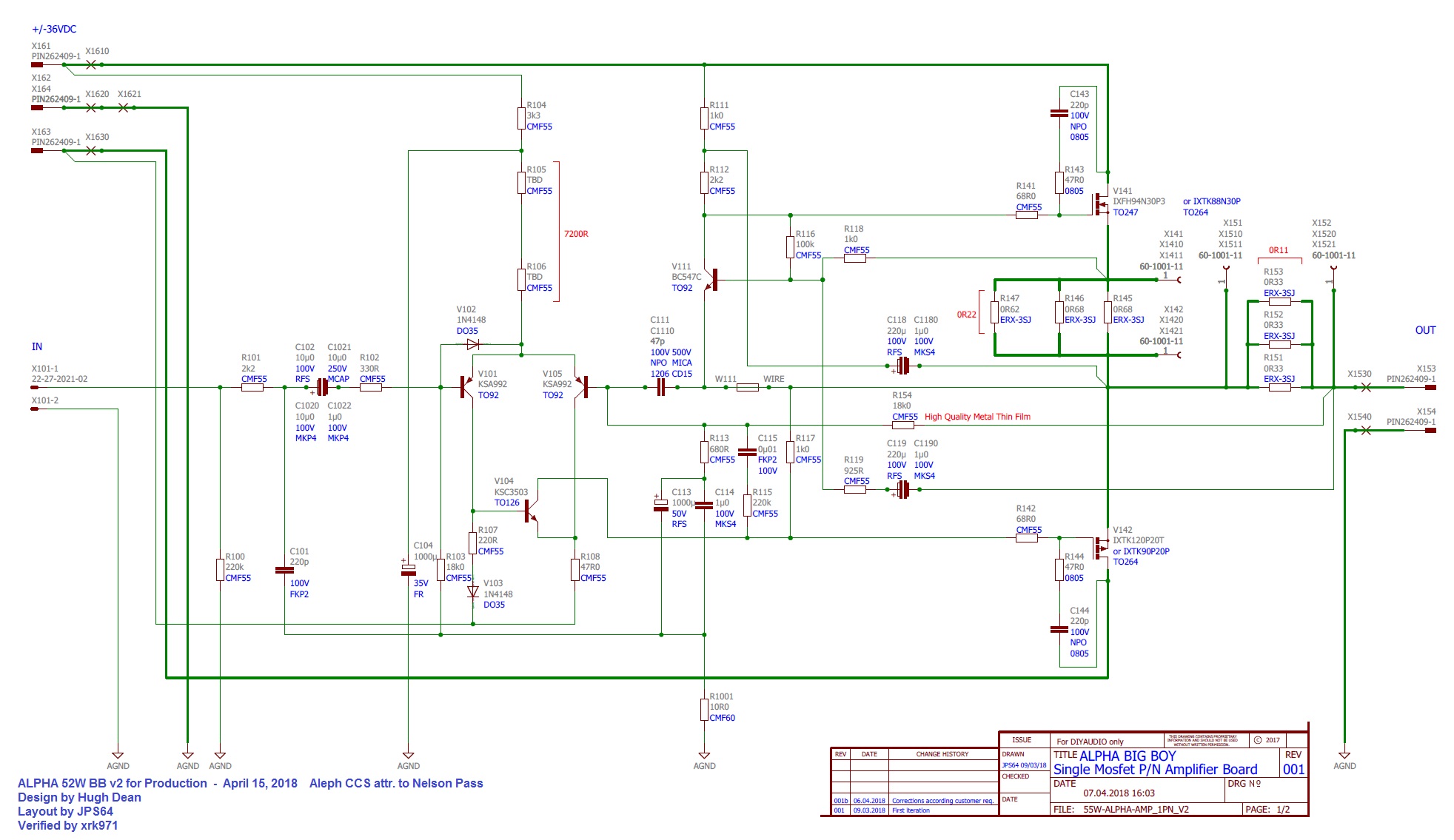
I don't believe the BB is set up for 4R loads. It's better than the ALPHA 20/8R, but still not good. You'd have to increase the quiescent to (32/4)/2, which is 4A. Then you'd have to change the R119 to 1k2 to equalise the output device swings.
Cheers,
HD
I have revisited the phase shifts and with 5pF the 0dB gain turns over at 2.8MHz.
You may be right; but I have only examined the single 240/9240 pair, rather than the three pairs which represent the Ciss and gms of the larger mosfets, so I will check again this evening and have an answer for you tomorrow.
Juntuin,
Indications show that a 25Vac secondary loaded to 3A with CRC pulls down the voltage to around 32V dc. A 30Vac secondary would probably give you at least 37-38Vdc and so I agree it's a better option. If there is too much voltage, reduce it with another RC network, giving you a CRCRC, or even increase the R on the CRC to say 0.5R or so. But take care that this resistor is rated to at least 5W.
Each of the Dell coolers is rated to, I believe, 130W maximum. I would not go over 100W each to keep down temperatures in all ambient situations, and if your BB is set up for more than 200W dissipation, I would not use just two. I'd go for four.
I don't believe the BB is set up for 4R loads. It's better than the ALPHA 20/8R, but still not good. You'd have to increase the quiescent to (32/4)/2, which is 4A. Then you'd have to change the R119 to 1k2 to equalise the output device swings.
Cheers,
HD
Last edited:
Juntuin,
Indications show that a 25Vac secondary loaded to 3A with CRC pulls down the voltage to around 32V dc. A 30Vac secondary would probably give you at least 37-38Vdc and so I agree it's a better option. If there is too much voltage, reduce it with another RC network, giving you a CRCRC, or even increase the R on the CRC to say 0.5R or so. But take care that this resistor is rated to at least 5W.
Each of the Dell coolers is rated to, I believe, 130W maximum. I would not go over 100W each to keep down temperatures in all ambient situations, and if your BB is set up for more than 200W dissipation, I would not use just two. I'd go for four.
Cheers,
HD
Ok, so I'm good with transformers I have already (two pcs of 2x30v 545va), good to know! Maybe I'll go with 0,5R power resistors just in case.
That's exactly what I meant, already have two Dells so I need to buy only two more and save money by doing so. Four Dells total, if they can handle the dissipation and their holes line up with B.B.'s holes.
That's exactly what I meant, already have two Dells so I need to buy only two more and save money by doing so. Four Dells total, if they can handle the dissipation and their holes line up with B.B.'s holes.
The Dell Fd841’s fit the mounting holes on the BB perfectly, no problems there.
The Dell Fd841’s fit the mounting holes on the BB perfectly, no problems there.
Awesome! This is going to be surprisingly cheap build at least for me then 🙂
Hi Juntuin,
I think Hugh and Vunce answered most of your questions. But to reiterate, a total of 4 Dell CPU coolers with fans is needed. I think the Dells typically don’t come with fans.
The breakout PWM fan controllers that JPs64 developed are designed to be controlled from the new microcontrolled VU meter/volume control/ fan control board. There may be a way to get it to work without the big smart master controller - JPS64 will have to confirm. I just bought the cheap COTS ones to get started and have a working amp.
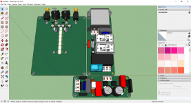
Yes, if you have the transformers already, this amp saves a lot on the cost of a big case with massive heatsink fins. So if you go for an open look case like my “amp on a plank”, that cost all of $10 for the “case”. The things that get you are the power capacitors for the CRCRC. And if you happen to have those too, then it’s the main BOM for the boards - which isn’t bad as there are only two outputs that cost about $25 a pair. Surprisingly inexpensive for a world-class amp.
I think Hugh and Vunce answered most of your questions. But to reiterate, a total of 4 Dell CPU coolers with fans is needed. I think the Dells typically don’t come with fans.
The breakout PWM fan controllers that JPs64 developed are designed to be controlled from the new microcontrolled VU meter/volume control/ fan control board. There may be a way to get it to work without the big smart master controller - JPS64 will have to confirm. I just bought the cheap COTS ones to get started and have a working amp.
Awesome! This is going to be surprisingly cheap build at least for me then.
Yes, if you have the transformers already, this amp saves a lot on the cost of a big case with massive heatsink fins. So if you go for an open look case like my “amp on a plank”, that cost all of $10 for the “case”. The things that get you are the power capacitors for the CRCRC. And if you happen to have those too, then it’s the main BOM for the boards - which isn’t bad as there are only two outputs that cost about $25 a pair. Surprisingly inexpensive for a world-class amp.
Last edited:
X,
I think the open case chassis is the better option right now. It’s a pain in the **s to get into my ALPHA20 every time I want to tweak something 🙄
I think the open case chassis is the better option right now. It’s a pain in the **s to get into my ALPHA20 every time I want to tweak something 🙄
...and separate fans for the Dell coolers are likely to cost more than the very cheap coolers X used, and the fans need to be able to push enough air through the coolers, so you need mounting clips for the dell coolers to mount fans or have higher temperatures, faster running fans etc etc, so the dell coolers will likely be the expensive option compared to coolers X used.
I wont worry about that, I have some Noctuas stashed and I bet there is not many as quiet fans at the market 🙂 I need only two more Dell heatsinks, that's it. B.B. have to wait some time though.
Last edited:
...and separate fans for the Dell coolers are likely to cost more than the very cheap coolers X used, and the fans need to be able to push enough air through the coolers, so you need mounting clips for the dell coolers to mount fans or have higher temperatures, faster running fans etc etc, so the dell coolers will likely be the expensive option compared to coolers X used.
It's hard to beat a mass-produced integrated product for cost and convenience. But my experience with the salvaged Dell cooler from the first vero board prototype is that a basic fan placed next to the cooler works quite well. If you don't mind mangling the aluminum fins a bit, a drywall screw on the corners of the fan can hold it in place on the cooler - right into the fin gaps. Or fashion some spring wire (piano strings) clips.
But if Juntuin has Noctuas already, they should work fine.
@vunce, I am glad my BB is open frame and parts on top - mods were a snap.
Last edited:
Yes, on B.B., Hugh suggested that I disconnect C111 and add 22pF NP0 (or silver mica) in parallel with R154 (feedback resistor). I did so and the top end sounds like it has more clarity, perhaps less distortion, it’s subtle but perceptible. I think it’s an improvement to an already great sounding amp.
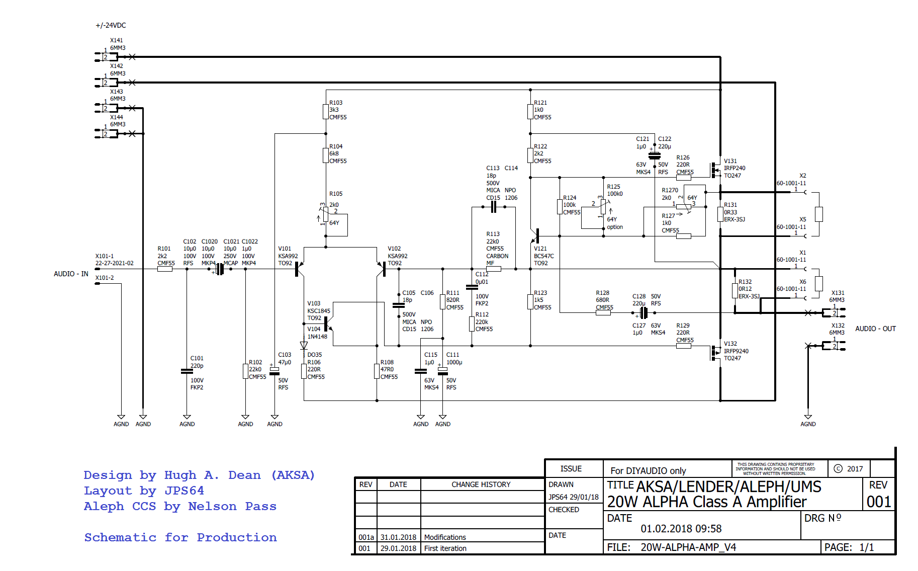
On Alpha 20 I guess it will be simply remove C105 and leave C113 at 18pF or increase to 22pF NP0 or silver mica - Hugh will confirm. It’s an easier operation on the Alpha 20 as the C113 is already there.
Could someone explain where and how the technical difference occurs when making those changes?
It would be interesting to know what is the parameter of the signal that changes and how much it does before the changes.
Best regards
Could someone explain where and how the technical difference occurs when making those changes?
It would be interesting to know what is the parameter of the signal that changes and how much it does before the changes.
Best regards
Hugh can give you the technical info but I think he told me before I made the mods that the changes would result in a improvement in the phase margin to allow the amp to have flatter phase well into the tens of MHz range! This would practically translate to better clarity of highs and improved spatiality/imaging.
Hi Hugh,
I've found some LTspice models of IXYS transistors.
I used them in the Alpha 4R simulation below, they seems to work.
Grts,
Danny
I've found some LTspice models of IXYS transistors.
I used them in the Alpha 4R simulation below, they seems to work.
Grts,
Danny
Attachments
Last edited:
Hugh can give you the technical info but I think he told me before I made the mods that the changes would result in a improvement in the phase margin to allow the amp to have flatter phase well into the tens of MHz range! This would practically translate to better clarity of highs and improved spatiality/imaging.
Thank you very much X. I will wait to see that technical information about the perceptible changes that are supposed to happen.
If the changes are subtle but perceptible, it should be possible to differentiate something in the measurements in relation to measurements prior to the change.
It would be interesting to know if the changes are due solely to a question of getting a flatter phase, or to changes in other parameters as well.
I was working hard these days to find technical support for this phenomenon, although according to the first results that I am analyzing, in principle, there does not seem to be a strict direct relationship with a more flat phase. There could be a relationship more directly related to the shape of the feedback signal that is sent to the base pin of one of the transistors of the LTP, when rapid changes of the signal in the output are presented (coinciding with signals of high frequency of the spectrum audible).
In B.B., it would be the signal that arrives at the base pin of V105. In Alpha 20, it would be the signal that arrives at the base pin of V102.
Based on the first tests with signals that suffer abrupt changes in their polarity and in their amplitude growth rate, it would seem that there is a certain range of capacitor values associated with part of the feedback network that would not negatively alter the shape of the feedback signal.
Best regards
PD: X, could you measure what is the shape of the signal on terminals of C113 (in the Alpha 20), when you find that optimal value that improves the spatiality / imaging, applying a square signal of 16 KHz?
Last edited:
Hi Danny,
Thank you for the models. I will put them in and have a good look at it.
I will take a few days to analyse all this stuff, but I would say that compensation is the most difficult aspect of amp design and I'm not wonderful at it because I ignore most of the math and do it empirically, or in this case, with X.
Let me attempt this during the day, again, my thanks to you and to Diego,
Hugh
Vout phase shifts on the ALPHA 20
Hi Danny,
I have done a bit of LTSpice analysis with a single pair of IRF 240/9240 outputs. This is a little simplistic, but it gives us the idea. Certainly a larger mosfet pair will slow things down and increase phase shift, but they are mosfets and they are in source follower where there is very little phase shift. Ergo, it won't make a lot of difference although it would be better to use them in the future when I have figured out how to incorporate into my Spice model directory. It should be easy with Notepad, but I'm not exactly sure at this point. Any help here?
The first graph is the original 18p + 18p compensation, one from collector of VAS (C1845) to ground, and the other from source of pmos back to fb node.
The second is the original 18p source pmos to fb node, with the other 18p dropped.
The third is my amended circuit with 22p across the 22k fb resistor, and the fourth is the amended circuit with Danny's suggested 5p across the 22k fb resistor.
They make interesting reading. We look for the phase shift from input to output when gain has fallen to 0dB. From this point on, nfb is transformed by phase shift into positive fb, but the amp cannot oscillate because it has no gain at this frequency. This defines Bode Stability. Only the compensation components, the topology and the active devices set this figure.
We find what frequency this 0dB gain lies at, and then how much phase shift is at the point, and try to ensure this phase shift is well under 360 degrees.
You should look at each graph at 0dB gain. The topology, compensation caps and devices this frequency. If the phase shift at this point is less than 360 degrees (input started at 180, so 360 represents a further 180 shift so that negative fb now is positive fb with the real danger of making an oscillator) and if the margin is less than 180 degrees of phase shift this becomes the phase margin and should be better than 30 degrees. A phase margin of 30 degrees would represent 150 degrees of phase shift at that 0dB gain point between input and output of the amplifier.
See if you can figure out what you should choose!
Hugh
Attachments
Last edited:
- Home
- Amplifiers
- Solid State
- Aksa Lender P-MOS Hybrid Aleph (ALPHA) Amplifier