Tomorrow I will send the next 3 packages.
sorry to bother you again 🙂
Is it shipped today?
Thanks Vitaly for the files. One more quick question, looking at the first post I see the amp is rated at 100-265vac which I presume that without any kind of jumper or anything else I can power up the amp using my 220-240VAC. Can you please confirm on the same?
Also I see a single standalone spade connector next to the fuse socket, what is that meant for? For the power I see 2 spade connectors beside the fuse for neutral/phase which goes to the wall socket. Do you have a connection from the IEC earth to the amp module?
Regarding the input signal wiring I see in one of your pics but would like to know from you which of the 3 pins belongs to signal/ground for left/right channels? I am going to use a single ended RCA signal as input and not balanced.
The same kind of confusion with the output spade connectors and I see there are 4 and in one of the pic I see your wiring but would like to know from you the connections as well as the right/left outputs.
Thanks
Manniraj - I am still waiting for my amp to arrive but once you figured out those connections perhaps you could post pics; diagram etc...? Thanks in advance.
Manniraj - I am still waiting for my amp to arrive but once you figured out those connections perhaps you could post pics; diagram etc...? Thanks in advance.
Sure I am waiting for Vitaly to provide some details otherwise need to see other build pics for the wiring connections. I could figure out the input signal wiring for unbalanced but still need to figure out the output connections for left/right.
Sure I am waiting for Vitaly to provide some details otherwise need to see other build pics for the wiring connections. I could figure out the input signal wiring for unbalanced but still need to figure out the output connections for left/right.
Thank you!

Sure I am waiting for Vitaly to provide some details otherwise need to see other build pics for the wiring connections. I could figure out the input signal wiring for unbalanced but still need to figure out the output connections for left/right.
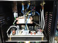
I have an earlier all-in-one board and the outputs are as in the attached photo. Black wires are Common while blue/yellow are the + leads with L & R marked on the board. “+” outputs go to a speaker protection board in my build. Hope this helps,
Pete
Attachments
Thanks Pete, the connections seems to be similar to my new green board. I will follow the same and check it out. Also in my last conversation Vitaly said not required to use a speaker protection module as its built-in but not sure as I don't see any relays on board. Then I need to figure out how to power the protection module.
Thanks
Thanks
I have an earlier all-in-one board and the outputs are as in the attached photo. Black wires are Common while blue/yellow are the + leads with L & R marked on the board. “+” outputs go to a speaker protection board in my build. Hope this helps,
Pete
Hi, why did you put another mains filter on the case?
Be careful with the speaker protection module, as most are designed for use in Class AB amplifiers where the "-" lines are connected to ground, which is not allowed in Class D amps.
Thanks zek, interesting I will wait for Vitaly to comment on the usage of the protection module in the newer version of the amp that he sent me in green pcb. I remember he told somewhere in the thread like the protection is in-built on the amp itself and does not need to have another one.
Rgds
Rgds
If you’re addressing the silver/metallic IEC box in the upper left, I just blindly use those as part of most common builds to filter the incoming AC (if room permits).
Pete
Pete
Hi, why did you put another mains filter on the case?
You can tap into the +/- 15VDC out line Vitaly put on the board if your SP module (specifically the voltage necessary to operate the relays) can use 15V or less or use a small, separate AC transformer (like I did) since my SP module has rectification as part of its circuitry. I used it because a got a bit of thump when I would turn the amp on. Vitaly didn’t tell me if there was any sort of SP module was built-in with my early version of his amp. If you get no thump when powering on/off then you may not want to use one. I’m presuming the LC output filter negates any concerns of DC output to the speakers?
Cheers, Pete
Cheers, Pete
Thanks Pete, the connections seems to be similar to my new green board. I will follow the same and check it out. Also in my last conversation Vitaly said not required to use a speaker protection module as its built-in but not sure as I don't see any relays on board. Then I need to figure out how to power the protection module.
Thanks
Last edited:
I used the SP module sold here in the diyAudio store and it only handles the “+” leads to the speaker output while the “-“ leads go directly from the amp to the RCA outputs.
Pete
Pete
Be careful with the speaker protection module, as most are designed for use in Class AB amplifiers where the "-" lines are connected to ground, which is not allowed in Class D amps.
- Home
- Group Buys
- Akita "AllInOne" Amp based on TPA325x PFFB+ and LLC PSU in one board.