Hi to all!
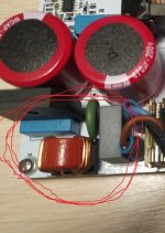
@drMordor, what do you think about the ferrites and RF/EMI filter? daniboun implementation of your TPA3255
This is good. If you have noises in your AC net from another gadgets, comp, DAC, tele, fridge, etc...
I not used this)))
No noise
I have a lot of problems with RF/EMI and DC at grid. Almost solved with some gadgets.
Some put their hands on their heads when used with Class D amplifiers like yours, hence the question.
BTW, to put ferrites, the one I always recommend is the Würth 150 kHz (I have a lot of in my two audio systems) and not the cheap 1 Mhz (video range)
Some put their hands on their heads when used with Class D amplifiers like yours, hence the question.
BTW, to put ferrites, the one I always recommend is the Würth 150 kHz (I have a lot of in my two audio systems) and not the cheap 1 Mhz (video range)
All my amps have a EMI filter.Some put their hands on their heads when used with Class D amplifiers like yours, hence the question.
Attachments
As a professional hardware designer of analog circuitry and smps I was responsible for CE marking of our products as well. Over a period of 20 yrs I spent a considerable amount of time in the EM-lab fixing problems to make stuff compatible with EU regulations. There is not much left you can tell me about these things. So you are not the only one to know something.@bucks bunny
I am the RF/EMI and ferrite man. I have many comments about them in some audio forums. I know something the subject, and better options, but the question is what the designer thinks.
The question is not what the desiger thinks, the question is which effect a certain measure provides in reality.
Obviously my comment is not welcome here.😱
xrk971 thanks.
PFFB+1565 ~15,9+9,5
I didn't do normal measurements, I will do it next week
Hi Dr Mordor,
Did you ever get around to making some measurements? Specifically, some 1kHz FFT spectra at 10w, and 50w would be appreciated. Either 4ohms or 8ohms. Would like to see if the on board SMPS is clean and how much (50/60Hz) leak through there is.
Cheers,
X
Hi xrk971
No, I am very busy at work until December 3, after I go on vacation, there will be a lot of time.
No, I am very busy at work until December 3, after I go on vacation, there will be a lot of time.

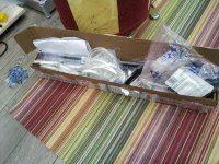

Hopefully the pcbs and 3255 will arrive soon.
For Christmas it would be a nice gift under the tree
For Christmas it would be a nice gift under the tree
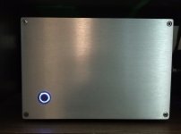
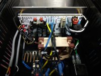
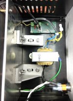
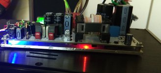
Here’s my AllInOne amp build
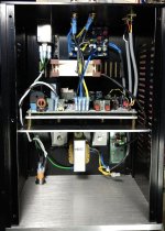
I decided to mount it slightly differently...on its side directly over one of the casing’s floor vents. This way a natural convection flow would bring heat from the heatsink out the vent in the top of the case. A JLE speaker protection circuit is driven by its own 15V transformer while drMorder’s board’s extra 15V (+ & GND) output is sent to a simple LM7812 circuit to drive a silent 80mm 12V fan placed directly in front of the amp’s on board transformer. Sounds fantastic. You all will be very happy once you get yours.
Cheers, Pete
Attachments
-
 391F97E9-A4B2-462C-BDDA-ADADE9782D05.jpeg229 KB · Views: 577
 -
 DB938AEE-A9EC-465F-93E3-FC423E5D6B9B.jpeg371.8 KB · Views: 554
 -
 0A06D371-D63A-4E0C-8F49-14A780967B13.jpeg340.7 KB · Views: 542
 -
 BA709C22-E2B4-46F0-BDF4-1CD008F0583F.jpeg391.5 KB · Views: 509
 -
 1110185F-4764-4E02-A1C0-A9E5C13675FA.jpeg334.7 KB · Views: 280
 -
 0C7FF992-50CF-4B38-96EF-1A0E4B8CF77C.jpeg292.3 KB · Views: 264
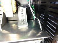
turion64 / drmodor, I'm curious how good is the thermal connection between the chip and a heat sink and how it is ensured? The chip height is exactly that of the standoffs? some thermal paste in between?
turion64 / drmodor, I'm curious how good is the thermal connection between the chip and a heat sink and how it is ensured? The chip height is exactly that of the standoffs? some thermal paste in between?
tmuikku: as Vitaliy has just stated his PCB is mounted on a thick aluminum plate and it is secured to the PCB in several places what look to be key areas (either side of the 3255 as an example) to assure proper heat transfer. When I ran the amp w/o being in the case the plate got quite warm indicating (to me at least) that it was doing its job. I mounted his amp to another aluminum plate so the sideways mounted scheme could be achieved. I could see some sort of paste where the chip meets his heatsink plate but could not tell if there was an extra connection metal plating in between the 3255 and the heatsink plate nor did I want to take everything apart to check. The extra fan I added is probably unnecessary.
I’ve run the thing for hours, continuously, w/o any issues, but I don’t listen to my music at extremely loud levels so I can’t claim to test the amps limits. The good Dr can give further clarifications.
Cheers, Pete
Ah, the PCB sized aluminium plate I see in the pictures is already attached at assembly by drMordor and included in the purchase? Great!
- Home
- Group Buys
- Akita "AllInOne" Amp based on TPA325x PFFB+ and LLC PSU in one board.