Hi folks!
I have an AKAI AM-U310 and after many years of music I lost the sound unfortunately.
Here is the story. I took an output for a mobile phone and I fed it into the AUX input.
Some seconds later the amp stopped.
What I have now. When I power up the amp I didn't here the click from the relay to operate.
After some research in this forum ( Amplifier Akai am-u33, powers on, but no sound ) I took some measurements to find out the cause of this fault.
All the AC measurements on the transformer was good the same as well with the DC on the bridge.
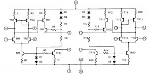
Then i have checked the fuse resistors FR1,FR2,FR3a,FR3b,FR4,FR5 out of the circuit and I found them ok.
Later i have checked the transistors TR1a,TR1b,TR2,TR3,TR5,TR6,TR7,TR8 and TR9 out of the circuit and I found them also good.
The final step was to take measurement on board with power on which I will demonstrate them below.
TR1a / TR1b
schem - measurements
B 0 - 0/-47.3V
C 14.4V - 0.3/0.4V
E 0 - 0/-47.3V
TR1b is bizarre.
TR2 and TR3 was ok
TR4 / TR5 TR4 / TR5
schem measurements
E n/a / n/a 0.01/0V
C n/a / 0.1 0/46V
B 14.3 / n/a -0.07/-0.9V
TR4 and TR5 have bizarre output.
TR6 / TR7 TR6 / TR7
schem measurements
E n/a / n/a n/a / n/a
C -0.6 / 0 -0.7/0V
B 9.6 / -0.6 9.1/-0.7V
TR8/ TR9 TR8 / TR9
schem measurements
E 21 / -20.9 20.9/ -21
C 26.6 / -21.6 21.6/-21.7V
B 40.9 / -43.1 43.1/-44.3V
And last but not least all the ICs
IC1 in equalizer board was great.
IC2 STK 3042
Pin / Scem in volts / measurement
1 / 0 / 0.1
2 / 0 / -1
3 / - / 43.5
4 / - / 44.1
5 / -1.1 / -44.7
6 / 1.2 / 44.5
7 / -43.3 / -43.5
8 / - / 0
9 / 43.3 / 43.6
10 / 1.2 / 1.2
11 / -1.1 / -1.2
12 / - / 43.1
13 / - / 43
14 / 0 / 0
15 / 0 / 0
So from pin 2 to 7 I have wrong measurements
IC3 STK 2250 SL
Pin / Scem - volts / measurement
1 / 1.2 / 1.2
2 / 45.5 / 43
3 / 0 / 0
4 / 0 / 0
5 / 0 / 0
6 / 45.5 / -43.4
7 / -1.1 / -1.2
8 / - / 0
9 / - / 0
10 / -1.1 / -43.5
11 / -45.5 / -43.7
12 / 0 / -43
13 / 0 / -43
14 / 0 / -43
15 / 0 / 43.5
16 / 1.2 / 43.5
Looks like that the half side doesn’t work properly.
IC4 LA6458S (edited 24/2/2020)
Pin / Scem - volts / measurement
1 / / 14.8
2 / -0.7 / -1
3 / 0 / 0
4 / 0 / 0
5 / -14.9 / -14.9
6 / / -7.8
7 / / 0
8 / / -13.3
9 / 15.2 / 14.8
Also here pins from 3 to 7 which are mirror one to each other have some not good measurements.
So looks like the problem passes from IC2 to the whole circuit and maybe TR 8 and 9 facing some difficulties because as I saw the have the ability to work with a switching time circuit 2SD612 pdf, 2SD612 description, 2SD612 datasheets, 2SD612 view ::: ALLDATASHEET :::
Also R36,37,38,39 were ok...
Can any one give me guidance how to proceed?
I have an AKAI AM-U310 and after many years of music I lost the sound unfortunately.
Here is the story. I took an output for a mobile phone and I fed it into the AUX input.
Some seconds later the amp stopped.
What I have now. When I power up the amp I didn't here the click from the relay to operate.
After some research in this forum ( Amplifier Akai am-u33, powers on, but no sound ) I took some measurements to find out the cause of this fault.
All the AC measurements on the transformer was good the same as well with the DC on the bridge.
Then i have checked the fuse resistors FR1,FR2,FR3a,FR3b,FR4,FR5 out of the circuit and I found them ok.
Later i have checked the transistors TR1a,TR1b,TR2,TR3,TR5,TR6,TR7,TR8 and TR9 out of the circuit and I found them also good.
The final step was to take measurement on board with power on which I will demonstrate them below.
TR1a / TR1b
schem - measurements
B 0 - 0/-47.3V
C 14.4V - 0.3/0.4V
E 0 - 0/-47.3V
TR1b is bizarre.
TR2 and TR3 was ok
TR4 / TR5 TR4 / TR5
schem measurements
E n/a / n/a 0.01/0V
C n/a / 0.1 0/46V
B 14.3 / n/a -0.07/-0.9V
TR4 and TR5 have bizarre output.
TR6 / TR7 TR6 / TR7
schem measurements
E n/a / n/a n/a / n/a
C -0.6 / 0 -0.7/0V
B 9.6 / -0.6 9.1/-0.7V
TR8/ TR9 TR8 / TR9
schem measurements
E 21 / -20.9 20.9/ -21
C 26.6 / -21.6 21.6/-21.7V
B 40.9 / -43.1 43.1/-44.3V
And last but not least all the ICs
IC1 in equalizer board was great.
IC2 STK 3042
Pin / Scem in volts / measurement
1 / 0 / 0.1
2 / 0 / -1
3 / - / 43.5
4 / - / 44.1
5 / -1.1 / -44.7
6 / 1.2 / 44.5
7 / -43.3 / -43.5
8 / - / 0
9 / 43.3 / 43.6
10 / 1.2 / 1.2
11 / -1.1 / -1.2
12 / - / 43.1
13 / - / 43
14 / 0 / 0
15 / 0 / 0
So from pin 2 to 7 I have wrong measurements
IC3 STK 2250 SL
Pin / Scem - volts / measurement
1 / 1.2 / 1.2
2 / 45.5 / 43
3 / 0 / 0
4 / 0 / 0
5 / 0 / 0
6 / 45.5 / -43.4
7 / -1.1 / -1.2
8 / - / 0
9 / - / 0
10 / -1.1 / -43.5
11 / -45.5 / -43.7
12 / 0 / -43
13 / 0 / -43
14 / 0 / -43
15 / 0 / 43.5
16 / 1.2 / 43.5
Looks like that the half side doesn’t work properly.
IC4 LA6458S (edited 24/2/2020)
Pin / Scem - volts / measurement
1 / / 14.8
2 / -0.7 / -1
3 / 0 / 0
4 / 0 / 0
5 / -14.9 / -14.9
6 / / -7.8
7 / / 0
8 / / -13.3
9 / 15.2 / 14.8
Also here pins from 3 to 7 which are mirror one to each other have some not good measurements.
So looks like the problem passes from IC2 to the whole circuit and maybe TR 8 and 9 facing some difficulties because as I saw the have the ability to work with a switching time circuit 2SD612 pdf, 2SD612 description, 2SD612 datasheets, 2SD612 view ::: ALLDATASHEET :::
Also R36,37,38,39 were ok...
Can any one give me guidance how to proceed?
Last edited:
A reference to a circuit (-drawing) or service manual might invoke more response. Yet, I have no clue whatsoever.
A reference to a circuit (-drawing) or service manual might invoke more response. Yet, I have no clue whatsoever.
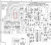
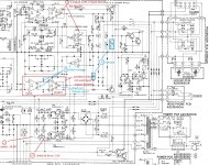
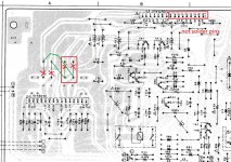
Hi MarsBravo you are right! Here is the service manual which i took under consideration.
Akai AM-U310 - Manual - Stereo Integrated Amplifier - HiFi Engine
Many mistakes in the pins and voltage measure of transistor and ICs.
According to voltage, the right channel power amp has problem(not sure the input IC or the ouput IC or both ICs)
May remove the two jump wire from the PCB for the problem right channel to see if your amp can operate with left channel only.
According to voltage, the right channel power amp has problem(not sure the input IC or the ouput IC or both ICs)
May remove the two jump wire from the PCB for the problem right channel to see if your amp can operate with left channel only.
Attachments

Many mistakes in the pins and voltage measure of transistor and ICs.
According to voltage, the right channel power amp has problem(not sure the input IC or the ouput IC or both ICs)
May remove the two jump wire from the PCB for the problem right channel to see if your amp can operate with left channel only.
Thank you for your replay patrick101.
I've made again measurements and i've edited ic4.
Now for you notices form 3 to 1
3) ic3 pin 4 gave 0v
ic4 pin 4 gave 0v
2) ic4 pin5 gave -14.9v
1) tr9 emitter -21.1v
collector -44.1v
base -21.7v
i've also remove the two wire jump wires but i didn't hear the click of the relay (RL1). and the measurement on ice on pins 10 to 14 gave -47v and for 15 to 16 gave 47v.
R59,R61 and D14 was ok!
Last edited:
half IC3 possible short circuit and need to replace, unplug the power and measure IC3 pin 11 resistance values to pin 12, pin 10 and pin 16 to check if there is low resistance.
with 2 jumper still open, remove two resistors and turn on the amp to see if the relay will work and measure the IC2 and IC4 voltages
with 2 jumper still open, remove two resistors and turn on the amp to see if the relay will work and measure the IC2 and IC4 voltages
Attachments
half IC3 possible short circuit and need to replace, unplug the power and measure IC3 pin 11 resistance values to pin 12, pin 10 and pin 16 to check if there is low resistance.
with 2 jumper still open, remove two resistors and turn on the amp to see if the relay will work and measure the IC2 and IC4 voltages
what i did is to take the stk2250 out of the circuit and to the measurements...
with multimeter in diode measurement i tried to face the pins as a single transistor... (see the pic) what i took was pins 16,15 shorted and 10,11,12 shorted in contrast with pins 1,2,3 and 7,5,6 which reacted as a single transistor.
Do i need to proceed in replacement of the stk 2250 or keep take measurements in case of other faulty part?
How possible is the stk 2250 to be burned without any other problem...
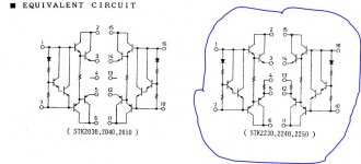
half stk 2250 is dead, you also need to test the input IC stk 3042 half channel ok or not, any short circuit or not. if stk 3042 is ok then replace the output stk 2250 should be ok
half stk 2250 is dead, you also need to test the input IC stk 3042 half channel ok or not, any short circuit or not. if stk 3042 is ok then replace the output stk 2250 should be ok
and so i did with stk 3042... crystal clear...😀
but i am still impressed how the output have been destroyed without any other problem... unless i didn't find it yet...
after i put back the stk3042 and with stk2250 still out i open up the amplifier and i heard the click sound from the relay...
Attachments
Last edited:
It is very hard to said how a ic breakdown, maybe a sudden high level signal input caused or something else, these power ic do breakdown easily
for the power ic stk 2250 pins 8-16, you can bend the pins forward or just cut them off and put back the PCB to test the other stk 3042 channel by remove old jumper and connect new jumper to test it, if stk 3042 all ok then you just need to replace the power ic stk 2250
if you can't find a stk 2250 ic, you can built it with discrete transistor, a simple 3 transistors and 3 resistors can built a channel
if you can't find a stk 2250 ic, you can built it with discrete transistor, a simple 3 transistors and 3 resistors can built a channel
Attachments
for the power ic stk 2250 pins 8-16, you can bend the pins forward or just cut them off and put back the PCB to test the other stk 3042 channel by remove old jumper and connect new jumper to test it, if stk 3042 all ok then you just need to replace the power ic stk 2250
if you can't find a stk 2250 ic, you can built it with discrete transistor, a simple 3 transistors and 3 resistors can built a channel
You were right! So i purchased the stk 2250 and changed it...
I have back my amplifier!!! 😀
 😀
😀Something more. Is there any problem to replace the electrolytic capacitors with slightly bigger voltage value?
Is there any problem to replace the electrolytic capacitors with slightly bigger voltage value?
For a small output amp, it is a good looking and sounding amp.
There is no problem to replace electrolytic capacitors with slightly bigger voltage value, just make sure the capacitor size can fit your PCB.
I am facing the exact same problem.
The relay works fine.
One channel is dead.
In frustration I hit the amp. FOr a few seconds it worked and then went back to working only on one channel.
THis post has been a big help to me even if I am still lost lol.
TR1 seems to be working but TR1b has zero voltage on all 3 pins.
The relay works fine.
One channel is dead.
In frustration I hit the amp. FOr a few seconds it worked and then went back to working only on one channel.
THis post has been a big help to me even if I am still lost lol.
TR1 seems to be working but TR1b has zero voltage on all 3 pins.
1. A relay "click" doesn't mean it's working good, the contacts inside maybe oxidized and caused bad contact. If the relay can be easily open and we can check and clean the contacts inside, otherwise we change a new relay
2. Speaker switches might be also bad contact, pls check and clean them if needed
3. If no voltage on transistor or hit the amp to working, there might be caused by PCB bad solder joins or broken PCB circuit, check the PCB circuit and joins, re soldering if needed
2. Speaker switches might be also bad contact, pls check and clean them if needed
3. If no voltage on transistor or hit the amp to working, there might be caused by PCB bad solder joins or broken PCB circuit, check the PCB circuit and joins, re soldering if needed
Old thread but triggered by a romanian post: as usual look up the type of the relay used and check if it has gold/gold plated contacts. When so (very often in older Japanese stuff) then replace for a sealed hard silver (bifurcated) contact version.
Speaker A/B/A+B switches are often a source for issues. It is best to just wire directly to the outputs.
Speaker A/B/A+B switches are often a source for issues. It is best to just wire directly to the outputs.
Hello! Sorry if my english is not good! Thank you from the bottom of my heart! This amplifier means a lot for me. Before it died out it was connected to PC, I was listening music at a relatively high volume and my PC is setted to enter in standby after no commands is performed and HDD and monitor stopped. In that moment I've heard a big boom sound and no sound in speakers after I've exit in standby. I stopped the amplifier and turned on and the click start sound no longer appeared and no sound in speakers. Also sometimes I had sound only on right channel together with a crackling sound from speakers on left channel. All being said you think that STK / STK's is broken? I want to make this amplifier to work as good as it can be. I'm sort of audiophile person. Kind regards!
@Martie1982 Your post must be in English for this forum.

- Home
- Amplifiers
- Solid State
- Akai AM-U310 relay doesn't respond