First One M owner of destroyed modules will be able to buy a Mirand amplifier that is drop in compatible[/B]
Yes we are going to make a drop in replacement for First One M. It is not a copy, and it is based on the Mirand A1 V1.2 technology but not as advanced and good. But still very good. Simply not space for a complete Mirand A1 V1.2 in those dimension.

Sonny,
If we modify our gain modules, do we have to re-adjust the trimmer?
Thanks
Do
Yes that is needed. Also when inserted into a new board... Always check
Yes that is needed. Also when inserted into a new board... Always check
Is the trimmer DC offset, bias? What's the adjustment procedure if bias?
Thanks
Do
Is the trimmer DC offset, bias? What's the adjustment procedure if bias?
Thanks
Do
Output in respect to GND. Rotate CCW or CW to get to below 2mV offset
I would like to hear how people want's the power transistors orientated on the MIRAND A1 V1.2 so that we can ship them out.
BR
Sonny
BR
Sonny
Output in respect to GND. Rotate CCW or CW to get to below 2mV offset
One last question about the gain modules modif. The 0603 resistors, what power rating is recommanded (1/4, 1/8, 1/10, 1/16, etc) ?
Thanks Sonny!
Do
One last question about the gain modules modif. The 0603 resistors, what power rating is recommanded (1/4, 1/8, 1/10, 1/16, etc) ?
Thanks Sonny!
Do
I use 1/10W but it does not matter because we have like 5 - 10mW at maximum in those resistors mentioned.
BR
Sonny
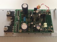
If the ones who have ordered would like to take a look on the picture and see if the assembly of the power transistor is okay!?
Then we could install the power transistors.
Vgeorge?
Vitalica?
Aboe?
Joseph K?
Ravid?
Steven?
By the Way that is 16 channel's until now... Thanks the interest and support in my products 🙂
BR
Sonny
Then we could install the power transistors.
Vgeorge?
Vitalica?
Aboe?
Joseph K?
Ravid?
Steven?
By the Way that is 16 channel's until now... Thanks the interest and support in my products 🙂
BR
Sonny
Attachments
Last edited:
I would like to hear how people want's the power transistors orientated on the MIRAND A1 V1.2 so that we can ship them out.
BR
Sonny
Could you please be more specific? A picture of the options would help.
Also I can confirm that Sonny' s after sale support is excellent so far.
When I had problem or when for an unknown reason burned on channel of an amp, Sonny was there to solve the problem.
If the ones who have ordered would like to take a look on the picture and see if the assembly of the power transistor is okay!?
Then we could install the power transistors.
Vgeorge?
Vitalica?
Aboe?
Joseph K?
Ravid?
Steven?
By the Way that is 16 channel's until now... Thanks the interest and support in my products 🙂
BR
Sonny
It looks fine form me, I don't know if there are other options.
Dear Sonny
This kind of preamp. Can you say its similar to the mark levinsons lnp2 or jc3 topology both discrete.
This kind of preamp. Can you say its similar to the mark levinsons lnp2 or jc3 topology both discrete.
If the ones who have ordered would like to take a look on the picture and see if the assembly of the power transistor is okay!?
Then we could install the power transistors.
Vgeorge?
Vitalica?
Aboe?
Joseph K?
Ravid?
Steven?
By the Way that is 16 channel's until now... Thanks the interest and support in my products 🙂
BR
Sonny
Transistor orientation is fine for me.
If the ones who have ordered would like to take a look on the picture and see if the assembly of the power transistor is okay!?
Then we could install the power transistors.
Vgeorge?
Vitalica?
Aboe?
Joseph K?
Ravid?
Steven?
By the Way that is 16 channel's until now... Thanks the interest and support in my products 🙂
BR
Sonny
Hi Sonny ,
I want under pcb (as in the picture).
Thank you.
Mirand A1 V1.2 description
Supernet has got the same info but:
I am Making a Manual that will be released later today.
The basic information right now is:
It is a Current feedback design, that I have been working for years and slowly have been updated on several point.
One thing that I value very high is that the idle current in every stage is stable. So a basic design gets a bit complicated because of my goal. It means for example that my VAS stage has fixed current of around 4mA, this in return gives a fixed impedance of the VAS stage. Again during heat up we have a stable openloop gain so that the amplifier has nearly the same sound signature from cold to warm state. Only part that drifts very slowly is the bias current of the output stage but that is due to heat up of the output devices from cold to warm state. This in return makes it very easy to set the Bias because we do not have a fluctation in VAS stage.
Some of the issues that can be a pain in DC coupled Current feedback is that we have a fluctation on the DC offset. Not much if done right but we have choosen to add a DC Servo because if the Source puts out DC it will get multiplied by the gain of the amplifier.
DC offset is monitored as well as supply voltage. We have an under voltage detect that trips below +/-21V.
DC offset + startup + under voltage lockout disables the SSR relay in the output. Which has a ON resistance of 8mOhm.
Only trimming necessary is Bias current.
The specs are:
Board size : 71x110mm
All bipolar design.
Minimum current consumption : 50mA
Minimum bias current : 25mA
Supply voltage : +/-24VDC to +/-50VDC
Slewrate : 300V/uSec
Bandwidth : 1.2MHz
Power rating at +/-46VDC : 80W@8R, 150W@4R, 250W@2R
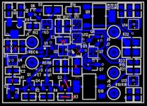
Correction!! Q5 should Also be removedNew Gain module and how to modify the previous version
We have a new Gain module on its way. It sounds better and the current is lower and less heat.
Now existing customers can change there modules if they are experienced in SMT assembly.
Look at the attached picture.
X = remove, If red line (Q3) then a short.
z = 0R 0603 resistor
Y = 620R 1% 0603 resistor
W = 22pF
The new Gain module cost 80€
Attachments
More sale
Hi Sonny,
You can add a set for me to the list. Transistor mount is the same as I use on my own amplifiers, so perfect for me.
BR Erik
Hi Sonny,
You can add a set for me to the list. Transistor mount is the same as I use on my own amplifiers, so perfect for me.
BR Erik
Correction!! Q5 should Also be removedNew Gain module and how to modify the previous version
We have a new Gain module on its way. It sounds better and the current is lower and less heat.
Now existing customers can change there modules if they are experienced in SMT assembly.
Look at the attached picture.
X = remove, If red line (Q3) then a short.
z = 0R 0603 resistor
Y = 620R 1% 0603 resistor
W = 22pF
The new Gain module cost 80€
Does it need to be jumpered like Q3?
Do
Hi Sonny,
You can add a set for me to the list. Transistor mount is the same as I use on my own amplifiers, so perfect for me.
BR Erik
Yes of course. You are added Erik.
- Home
- Vendor's Bazaar
- AK4490 USB Dac with dsd support.