Do the contacts for it come out to a point where you can check it with a multimeter to see if the resistance across it is different than the other switches?
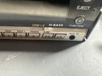
On the diagram, it appears that the PS switch connects to pins 1 and 2 of the connector CON603.
On the diagram, it appears that the PS switch connects to pins 1 and 2 of the connector CON603.
I hit the button with some deoxit and it clicks but better but still no change
I found it and there is no difference in resistance
I found it and there is no difference in resistance
Last edited:
If you don't read 0 ohms between the RCA shields and the case of the head unit, someone likely let 12v contact the shields and burned the inductor.
There wasn’t any resistance between the two but I decided to take the inductor out to test it, sure enough tester said it was not working, is there something I can substitute it with to see if that was the issue?
A piece of wire, a 1 ohm resistor... It's not critical and if it makes a difference, the diagram has errors. This is only for the RCA shields.
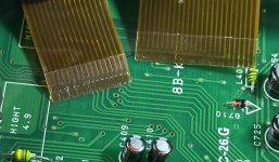
There are some scratches on the ribbon cables, do any of them go deep enough to cut through the copper?
There also appears to be some bare copper. Do you see those areas or is it just an artifact in the photo?
There are some scratches on the ribbon cables, do any of them go deep enough to cut through the copper?
There also appears to be some bare copper. Do you see those areas or is it just an artifact in the photo?
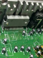
After I took L401 out I took L402 out to see if they both tested to same to double check if L401 wasn’t working and broke one of the legs of L402 putting it back in, so it wasn’t a previous issue
If you can't solder a wire to the remaining part of the leg on L402, use a wire to replace it.
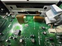
If you leave the ribbon cables disconnected, do you see more activity on the pins of the MCU?
If you leave the ribbon cables disconnected, do you see more activity on the pins of the MCU?
- Home
- General Interest
- Car Audio
- Aiwa CDC-MP32 Headunit Unresponsive