I did try this, but somehow I can’t understand the results yet, maybe later 😉 thank youOne more thing 😉 - RMAA lacks the concept of soundcard calibration file. But it does have a button for subtracting one measurement result set from the other (there is a minus-button in the results window).
If you subtract the loopback results from device measurement results then you have eliminated the soundcard effect - at least theoretically speaking...
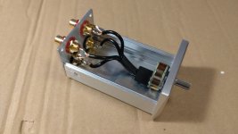
I made my own adaptors from speakers outputs to rca.
Then measured the response of the whole amp from rca inputs to speakers output at half volume (19/44 clicks of volume pot).
The difference btw channels was even higher to get measuring signal proper

Then measured the response of the whole amp from rca inputs to speakers output at half volume (19/44 clicks of volume pot).
The difference btw channels was even higher to get measuring signal proper
Then the results seem to be quite worse too, as expected.
I can not go for much higher amp output as this was already adjusted down to 2% of laptop volume output.
I am curious what I can estimate from the results now..


I can not go for much higher amp output as this was already adjusted down to 2% of laptop volume output.
I am curious what I can estimate from the results now..
2% of soundcard volume output is too low - I have used min 45%, less caused signal distortion if my memory serves me right.
You should use a 10k pot over the speaker terminals (wiper connected to soundcard input), set it to min position and adjust the windows mixer output to the level you used for preamp (or e.g. 70% to start out with).
Set the volume knob to the position when you measured the preamp.
Then start SLOWLY turning up the pot on the terminals (signal fed back to soundcard). If you turn it too high then you will fry the soundcard input stage.
Until you are below 0dB in RMAA levels it should be ok.
And you should use a pair of 5W 8 ohm resistors to provide the actual load to the output stage - you can connect them via speakers switch on and off to see any changes in the spectrum.
To verify the actual disbalance between channels - play 1kHz (or 400 Hz) tone from computer to amplifier and measure AC values (with a simple DMM) both at preamp output and power amplifier output - this will show you the problem "in numbers".
Thank you for the advice. Is possible to generate the 1kHz continuous signal directly from RMAA or do I need to use different software?To verify the actual disbalance between channels - play 1kHz (or 400 Hz) tone from computer to amplifier and measure AC values (with a simple DMM) both at preamp output and power amplifier output - this will show you the problem "in numbers".
RMAA does not have a signal generator.
Use Zeitnitz scope (soundcard scope software, free for personal ues, pretty easy to use, one of my favourites before I bought oscilloscopes) generator or generate a sine wave into a sound file with Audacity and play that file.
Or find a suitable wave file from internet (should be easy search) and play that. There should also be online generators but I have not used them so my knowledge is limited.
Thank you. I am lucky having simple passive preamp with 10k pot, also found 8.2Ohm 5W resistors, all connected and ready like this..You should use a 10k pot over the speaker terminals (wiper connected to soundcard input), set it to min position and adjust the windows mixer output to the level you used for preamp (or e.g. 70% to start out with).
Connect the resistor as B-speakers and take the output signal (to pot) from A-speakers terminals.
Then you can switch the load (on B-terminals) on and off to monitor the potential change.
Then you can switch the load (on B-terminals) on and off to monitor the potential change.
Looks like a good starting point to me.First, the PC volume was around 52%, this is the result:

Thank you.Use Zeitnitz scope
The software is installed and I have generated 1kHz frequency directly from there.
Then I have measured the rca pre outputs and speaker outputs both at 19/44 volume:
Pre out 19/44:
Left 272.7mV
Right 292.8mV (about 7.3% more)
Power out 19/44:
Left 6.46V
Right 7.14V (about 10.5% more)
Then I also checked just pre out at fully open volume pot:
Pre out 44/44:
Left 1.570V
Right 1.589V (about 1.2% more only)
👍 mine is possibly not perfect too, but I am happy I have at least something 🙂the pot had differences between channels in the first 30% of the working area.
This is not clear to me. Should I connect additional 8W resistor across the + and - poles of each channel of B speakers to simulate additional load while testing the A speakers again?Connect the resistor as B-speakers and take the output signal (to pot) from A-speakers terminals.
Then you can switch the load (on B-terminals) on and off to monitor the potential change.
Yes, connect the (single pair of) 8R resistors to B-speakers terminals (as you would do with the speakers) and switch the B-speakers (8R load) on and off to check for any visual change in the spectrum (before measuring). Results of amplifier with nominal load present may differ from results without load.
Soundcard signal would be taken from A-terminals. If both speaker outputs will be switched on from the knobs on front panel then these terminal sets will be connected in parallel.
I would solder some piece of wire to the resistors - should they get hot during measurements then you can drop them into a glass of water (two glasses actually - you do not want them to contact each other).
Ok, did connect those additional resistors

There is a little drop when A+B speakers are selected (0.3dB)


Then the results are even worse, and some strange value in THD (swept freqs) window

The resistors became hot, but I did just one test, so ok..
There is a little drop when A+B speakers are selected (0.3dB)
Then the results are even worse, and some strange value in THD (swept freqs) window
The resistors became hot, but I did just one test, so ok..
Also Stereo Crosstalk dropped from -61.9dB to -40.4dB compared to only A speakers output test..
Not sure what those all values are saying and what to focus on..
Not sure what those all values are saying and what to focus on..
- Home
- Amplifiers
- Solid State
- Aiwa AA-8300 restoration ideas