It should be a UF4007 or 1N4007. It only protects C5 on start up while the negative supply is alive, but the rectifier tube isn't hot yet, After that it's reverse biased.....so any diode that will stand whatever your B+ is will work fine.
Thanks for the find, BOM is being fixed and will be uploaded shortly to post #1
Thanks for the find, BOM is being fixed and will be uploaded shortly to post #1
Last edited:
Hi George, any insight into Q's #2-#5? Will move to a different thread if that is more appropriate. Thanks
2) Edcor transformers are blue. This would look funny if you used any OPT other than Edcor. The 200 series Hammonds are good, but the 300 series Hammonds are better. They don't run as hot and are less likely to buzz.
I am currently using a 372HX in my amp but my B+ is over 350 volts depending on what tubes I use and how much current I run. This works with 300B's and some 2A3's, but is too much voltage for 45's. I run a little Allied transformer with the 45's because they are cheap. It's really a Hammond in disguise somewhere in between a 270DX and a 270EX. B+ is about 320 volts with 45's and a 47 uF cap for C4. Reducing the cap will drop the voltage, but I have run 45's at 320 volts for years without issue.
The 370EX or 370FX are probably good choices, or get the 370HX with the 6 amp heater winding so you could pop 2A3's in the amp if you so desired.
3) The Triad C-14X choke is the budget option, and it's ugly, so I hide them under the deck. I currently have a C-17X which isn't optimal, and is one of the reasons for my high B+. For a no-budget restrictions build, go for the Hammond choke.
4) Yes, the Kemet cap in the BOM is the best part I could find in regular distribution, and with a motor run cap in parallel, perfect.
5) You want a Polypropylene cap of at least 370 VAC and 40 or more uF. I have always used motor RUN (not START) caps because they are designed for continuous high current and direct connection to the power line. This means they have to be good (low ESR, ESL...) or they EXPLODE! Beware of Ebay sellers passing off motor START caps as motor RUN caps. If it's black plastic, don't use it unless you are sure it's polypropylene. These will not live! The silver can you showed in another post is fine. I can't keep track of all your different threads, so I don't know where I saw it, but I think it was an ASC. They are excellent.
2) Edcor transformers are blue. This would look funny if you used any OPT other than Edcor.
Even if you plan on repainting all your tranformers so they match, the other downside of the edcor ones is that they are built to order so your lead times are much longer. Lots of places stock the hammonds for next day delivery.
Thanks alot, all the information is exactly what I needed.
The last piece of the puzzle is the transformer. I am debating between an 8, 16, 32 or 8+32 secondaries.
HP's will always be in the 32-300 range. In all cases, I can add resistors across to create a 5K reflected load.
So the question is, is there any difference between a 8ohm secondary or a 32ohm (assuming both have resistors to match 5K reflected load)?
How does that affect the available voltage and current available to the HP's?
Last edited:
3) The Triad C-14X choke is the budget option, and it's ugly, so I hide them under the deck. I currently have a C-17X which isn't optimal, and is one of the reasons for my high B+. For a no-budget restrictions build, go for the Hammond choke.
On Tubelab.com, you mention:
If you need a better looking choke, use one that has nearly 150 ohms of resistance, and has the same or higher current rating as the power transformer.
The Hammond 158M is rated at 100mA DC current.
Any of the relevant PT's are 140-170mA... so is this one still good?
The only other chokes in this series have lower resistance which I assume is not great as it would increase B+
I do a lot of DIY stuff, and have found that 1N4007s and UF4007s are so cheap, ubiquitous and useful that it's worthwhile to throw in 10 or 20 on a normal parts order. I've done this on several occasions and have never regretted it.
Thanks, if you want another inconsistancy, at least, I found another. On the board you have IC1 to 3 but in the BOM, you have U1 to 3. I think IC3 is U1 and IC1 U3, with IC2 = U2.Thanks for the find, BOM is being fixed and will be uploaded shortly to post #244
Hopefully this is correct, as that is what I have soldered them as 🙂
Thanks, if you want another inconsistancy, at least, I found another.
Thanks. I see and work with these boards daily. I have worked with the TSE design for over 15 years. Little details like these get overlooked by me since I don't even look at the parts list to put the same parts in the same holes that I have done for years.
In the process of fixing this, I found a similar inconsistancy with the tube sockets....both are fixed. I am posting the revised BOM in post #1 to make it easy to find. ALL new BOM updates and important build info will go into post #1. The BOM in post #244 will disappear.
If anyone finds anything else questionable please post it here. It's easier to fix it now than to unravel the trail of confusion later. I have been building tube stuff for over 50 years. Something that is obvious to me is often not obvious to others.
Last edited:
Here is my build so far. Wasn't quite sure which way round the ICs should go, and something I need to and will learn, but in this case I copied Georges build from his pictures earlier, so hopefully they are OK or I have a bit of extra work to do. Have only had to use the solder sucker once so far, after a mistake when I was tired late last night, but all fixed now 🙂 Heat sink soldering was a bit challenging, since they are, well, head sinks, so not the best soldering.
Attachments
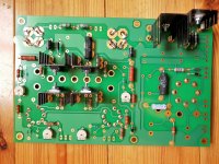

I compared your picture to my working board and I don't see anything obviously wrong. I will give it another look when I can disconnect my board and bring it to the computer screen.
I don't always solder the heat sinks at all. If the board is going into an enclosure and it's not going to get banged around, they aren't going to move. My two boards are constantly being moved, poked and prodded. I soldered one pin.....and it's not such a good job either.
I don't always solder the heat sinks at all. If the board is going into an enclosure and it's not going to get banged around, they aren't going to move. My two boards are constantly being moved, poked and prodded. I soldered one pin.....and it's not such a good job either.
I can't keep track of all your different threads, so I don't know where I saw it, but I think it was an ASC. They are excellent.
Very sorry for that! I will do a better job searching through the existing threads as most of my questions have probably been answered dozens of times at this point.
I finished stuffing my tse II board this morning (except for d7). Once that comes in I can try to power up. I am assuming the basic steps from the tse assembly manual for checkout and biasing are pretty much the same -- please give a quick warning if there are any gotchas. On my SSE, I had installed an Inrush Current Limiting Thermistor -- is one recommended for tse II as well?
Optional parts to add to the bom:
Everything went together pretty well -- similar to the SSE but more of it...
All the ic's except for d1, had two mounting locations for the heat sinks so you can mount on either side of the board and still have the heat sink contacting the chip on the right side. I had a hard time figuring out how to make it work with d1 and it looked to me like everyone had it installed backwards in their pictures until I found the comment on post 251 that d1 is reversible! I'd recommend adding that to bom notes item 4!
Allen
Optional parts to add to the bom:
- Heat Sinks Mounting Kit with Thermalsil III for TO-220 (4880SG) (mouser part number 532-4880SG). Whether you need the insulator or not, you definitely need screws, washers, nuts and it is a convenient (and pricey) way to make sure you have what you need.
- PC Board Terminal Blocks (5 x 2 connection, 4 x 3 connection) (Mouser 651-1715022 and 651-1715035)
Everything went together pretty well -- similar to the SSE but more of it...
All the ic's except for d1, had two mounting locations for the heat sinks so you can mount on either side of the board and still have the heat sink contacting the chip on the right side. I had a hard time figuring out how to make it work with d1 and it looked to me like everyone had it installed backwards in their pictures until I found the comment on post 251 that d1 is reversible! I'd recommend adding that to bom notes item 4!
Allen
OK, I have a question about the tubes being used in this design.
I checked the BOM and see there are five according to it showing V1-V5. Since I keep seeing the “300B” being mentioned I checked the Western Electric 300B pinout and it is a 4 pin design. So that covers V3 and V4, but can someone please clue me in on the other three tubes? Thanks.
And damn those WE 300B tubes fetch a nice price.
James
I haven't built mine yet, but based on the instructions on the site,
the 9-pin would be the input tube, 5842/417A, and the 8-pin would be the rectifier, 5AR4
See "Tubes" section:
Tubes and Applications | Tubelab
the 9-pin would be the input tube, 5842/417A, and the 8-pin would be the rectifier, 5AR4
See "Tubes" section:
Tubes and Applications | Tubelab
Cool, thank you again!
May I ask what PT and OT you picked up? I do not see them in the BOM or build thread on his site? Thanks.
James
Sockets? Check.
Power Transformer? Check.
OPTs? Check.
Chassis material and fasteners? Check.
Now for the Mouser order and the PC board (it may be later this week though as I couldn't make it to the Post Office this morning). Still thinking up ideas for a chassis design - something tasteful, but functional.
In the interest of heeding the advice in notes 3, 4 and 6, I'm going ahead and adding four heat sink insulator kits while I'm at it, just in case.
May I ask what PT and OT you picked up? I do not see them in the BOM or build thread on his site? Thanks.
James
- Home
- More Vendors...
- Tubelab
- After a 14 year run, the TSE must DIE!