Floor bounce
Is floor bounce a big or small problem? TLDR: small
My speakers and my hearing: no other humans were exposed to harm.
The measurements in the 4th plot of #35 show obvious (multi-arrival) response changes in the octave above middle C. To see what effect those have on the perceived sound, I tried to move my head straight up and down between where the mic was for the blue and green traces. The floor is suspended, wooden (smooth, decorative wood top, foam underlay, plywood on suspended joists), and was bare between the speakers and my ears.
I tried several kinds of music, but ended up listening mostly to orchestral strings with bowed and pizzicato sections. These recordings contain good proportion of the energy in the relevant octave and let me listen for tone changes and imaging at the same time. While writing this I went back and forth to check some impressions on three different recordings of Sibelius' 7th symphony.
I've spent a few minutes now and again, with nobody watching, propping myself up on my arms above a short stool, moving up and down and pausing for a few seconds at each position. Keeping my head vertical turns out to be essential to give a chance of hearing an effect from floor bounce.
The impression I got is of a minor change of timbre that quickly vanished from consciousness so that I had to concentrate to keep it in mind. A few degrees roll or yaw of my head caused much stronger changes that also fade from experience, promptly. I guess that gives a clue to the type of adaptation that's going on.
With effort, I could convince myself that there is a dullness one way (down) and a brightness the other (up). I didn't notice any effect on imaging - any such effect is small compared to even a tiny yaw of my head.
It probably shouldn't be a surprise that head rotations produce much larger effects, but there's a lot of discussion and effort put into floor bounce, which made me wonder, for a while. I could be missing something, if so, I'm content with that on this occasion - I don't want to learn to hear it.
Ken
Explaining my choice of driver spacing and crossover frequency
Thanks to kimmosto for posts that helped to clarify thinking on crossover design in the context of early reflections and power response.
Preamble:
There's no perfect speaker for your room or mine. Hopefully we find a design that comes close enough that months listening to music bring new experiences, even if the speakers turn out not to be the "ultimate".
A big help for me in the past half-year or so has been the Toole/Spinorama approach.
In the horizontal plane, the consensus appears to be to seek smooth DI to achieve good control of early reflections and power response. Dipoles can give reasonably constant horizontal directivity over a wide band (e.g. 100Hz to 10kHz).
Here I consider the vertical dimension which seems less settled.
My thinking was helped by reading comments by Kimmo Saunisto
such as: https://www.diyaudio.com/forums/multi-way/371070-talk-xo-10k-hz-1-4-wl-law-2.html#post6621599
What's important in the vertical plane, when our ears are usually horizontal?
The early reflections are mostly floor and ceiling, and there's a vertical contribution to power response.
I'm nearly convinced that floor bounce is less important than ceiling bounce - perhaps due to over two million years of standing upright on the floor, one way or another.
I looked at several examples of crossover design and driver spacing including some using VituixCAD - this is the probably best way to see the effect on power response.
For the quick plots I used Xdir - to aid thinking, all that's really needed is to know the angles of the cancellation nulls.
For sub-quarter-wave spacing there are no cancellations, so the response the vertical plane at any is determined by the polar response of the drivers, summed in power. This is often the goal of people making big waveguide speakers or coaxial designs.
The situation I faced in the design of the OBs suggested ~1.4 wave spacing due to the size of the GRS mid and tweeter and 3kHz crossover. Is that good or bad? Following from this, what is the appropriate bass-mid crossover to use in conjunction?
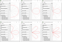
The attached simplified, illustrative, Xdir plots represent an ideal even-order crossover so the main lobe is horizontal. I put it arbitrarily at 1kHz.
The top row shows driver spacings of 1/4 wave, 1/2 wave, 2/3rds wave. The lower row has 0.8, 1.4 and 1.67 wave.
Nothing much happens from co-incident drivers up to 1/4 wave spacing.
The range from 1/4 to 1/2 wave provides a slowly increasing dip, at the crossover frequency, in the ceiling early reflection depending on ceiling height and listening distance. There's a dip in the power response.
Still larger spacing produces a stronger dip in the ceiling early reflection - even a null. I don't believe that is desirable.
Depending on the listening distance and ceiling height, there should be a solution where the lobes are aligned to make the ceiling bounce flat (for me near 1.4 wave spacing). The price that is paid is a much narrower main lobe with nulls above and below.
The narrow main lobe is fine for seated listening, the price paid is response dips experienced when walking around the room, at certain distances.
Ken
Thanks to kimmosto for posts that helped to clarify thinking on crossover design in the context of early reflections and power response.
Preamble:
There's no perfect speaker for your room or mine. Hopefully we find a design that comes close enough that months listening to music bring new experiences, even if the speakers turn out not to be the "ultimate".
A big help for me in the past half-year or so has been the Toole/Spinorama approach.
In the horizontal plane, the consensus appears to be to seek smooth DI to achieve good control of early reflections and power response. Dipoles can give reasonably constant horizontal directivity over a wide band (e.g. 100Hz to 10kHz).
Here I consider the vertical dimension which seems less settled.
My thinking was helped by reading comments by Kimmo Saunisto
such as: https://www.diyaudio.com/forums/multi-way/371070-talk-xo-10k-hz-1-4-wl-law-2.html#post6621599
What's important in the vertical plane, when our ears are usually horizontal?
The early reflections are mostly floor and ceiling, and there's a vertical contribution to power response.
I'm nearly convinced that floor bounce is less important than ceiling bounce - perhaps due to over two million years of standing upright on the floor, one way or another.
I looked at several examples of crossover design and driver spacing including some using VituixCAD - this is the probably best way to see the effect on power response.
For the quick plots I used Xdir - to aid thinking, all that's really needed is to know the angles of the cancellation nulls.
For sub-quarter-wave spacing there are no cancellations, so the response the vertical plane at any is determined by the polar response of the drivers, summed in power. This is often the goal of people making big waveguide speakers or coaxial designs.
The situation I faced in the design of the OBs suggested ~1.4 wave spacing due to the size of the GRS mid and tweeter and 3kHz crossover. Is that good or bad? Following from this, what is the appropriate bass-mid crossover to use in conjunction?
The attached simplified, illustrative, Xdir plots represent an ideal even-order crossover so the main lobe is horizontal. I put it arbitrarily at 1kHz.
The top row shows driver spacings of 1/4 wave, 1/2 wave, 2/3rds wave. The lower row has 0.8, 1.4 and 1.67 wave.
Nothing much happens from co-incident drivers up to 1/4 wave spacing.
The range from 1/4 to 1/2 wave provides a slowly increasing dip, at the crossover frequency, in the ceiling early reflection depending on ceiling height and listening distance. There's a dip in the power response.
Still larger spacing produces a stronger dip in the ceiling early reflection - even a null. I don't believe that is desirable.
Depending on the listening distance and ceiling height, there should be a solution where the lobes are aligned to make the ceiling bounce flat (for me near 1.4 wave spacing). The price that is paid is a much narrower main lobe with nulls above and below.
The narrow main lobe is fine for seated listening, the price paid is response dips experienced when walking around the room, at certain distances.
Ken
Attachments
The importance of location
I've spent a few weeks listening and listening more, with the OB speakers moved a few inches back and forth, left and right.
While it's hard to pick out subtle differences in measurement at the listening position, it is oh so easy by ear. Several times I've found that with my speakers, in my room, everything gels when they are 1.75+/-0.05m from the front wall, and 1.5+/-0.05m from the side walls.
The differences caused by 0.3m/1 foot of speaker position are roughly as great as the differences among all the speakers I've made (or set up) in the past decade.
Even moderately large adjustments of crossovers etc. are much less important than finding the right location. By some strange fortune, I'd found almost the best place on my first try of these speakers, my impression might have been very different had I set them up a foot or so from where I chose at the start ...
Persist!
Ken
Updates, for the record: crossover slope
Stimulated by discussions on several other threads, and since I could change the filters easily, I tried LR12 (2nd order) and LR48 (8th order) filters, in comparison with the LR24 described above. I couldn't achieve both crossovers at LR48 due to running out of EQ resources on the DCX2496, so tried one at a time, with the other at LR12 (to free resource).
Observations from measurement (with Holm Impulse, as above):
I'd already noted that the GRS mids have low distortion with the default filtering. I looked for signs of stress at high-90s dB SPL at 1m with 2nd order filters, and did not see anything concerning.
Therefore, I felt free to try 2nd order for both crossovers. With EQ, and inverting the mid, I got almost the same frequency response on-axis and up to +/- 30 degrees.
Changing either crossover to 8th order required adjusting the EQ as well.
The only conspicuous change resulting from these measurements is the floor bounce is less pronounced with the 2nd order lower filter. Other differences are minor changes to the off-axis response around the upper crossover, at the ~1dB level.
Observations by listening:
After cycling through the options for a while, I couldn't convince myself that I preferred any of these over the others. I ended up with 2nd order for both crossovers to allow maximum resources for future EQ tweaks, though I never actually made such changes.
Reasoning: when the drivers are working within their comfort zones, even with loud music, and the frequency response on and off axis are close to what's wanted, there's little motivation to increase crossover order. Possibly the group delay of 8th order crossovers is audible in specific circumstances, it seems unlikely to be the case for 4th order, and I couldn't/can't think of a reason to prefer on or other of 2nd and 4th order...
Over several weeks I made two other changes, described in the following posts.
Ken
Updates, for the record: Hypex FA123 amplifiers
Since my DCX2496s, amplifiers etc., are getting old (~15 years), I decided to look for a solution to make the OBs "active" fed by balanced XLR or digitally rather than having six sets of speaker cables trailing across the floor (under small mats). After some thought, I decided to try a pair of Hypex FA123 DSP plate amplifiers as a convenient solution. I knew from measurements that these would provide plenty of power even for loud music taking the OB boost into account.
I made semi-open boxes for the amps - ventilated, yet safe for the otherwise exposed voltages. They sit behind the dipoles, behind and below the bass drives.
There's slight hiss from the midranges which are over ~105dB 2.83V around 9kHz - they can be heard a foot or two away in a quiet room. I could transfer one pole of lowpass EQ from DSP to a series inductor (I'd try 0.2mH or so) to reduce out of band hiss, but I don't think I'll bother. The tweeters are ~12dB less sensitive and hearing his requires placing ears close to them.
The crossover and most of the EQ filters transferred over to the FA123 DSP quite easily. It took a little thought to translate the shelf filters that I used for the two GRS drivers. I decided to set them up anew, as I needed to check and set the gains of the various amplifiers anyway. As the speakers are ~5m apart, I used a laptop to program the DSP but measured using my normal music PC, with Holm impulse, rather than from the Hypex software. For me this was no inconvenience.
As well as the 2nd order LR crossovers, described above (650 and 3530 Hz), the tweeters only need a shelf, about same as with the DCX2496.
For the midranges, I could replace the shelf filter with a 1st order lowpass at about 3.5kHz and added a gentle notch at 9kHz. This change only took a few minutes once I got familiar with the Hypex Filter Designer (HFD) software.
The bass is set up exactly as with the DCX2496, as are delays etc. (there's a different absolute delay, but that's not important).
I'm using ~1/4 of the DSP resource.
The Hypex software is mostly straightforward. At first I couldn't get projects to show in the recent projects list - later it seemed to work as I'd expected (file menu, save as, load ...).
It already takes less time to set up filters using HFD than with the interface on the DCX2496 - it's easy to see what each biquad is doing and how to set the parameters.
Provided IIR filters are what's needed, these units are a very convenient way to make active speakers. Since the speakers have close to my target on-axis and polar responses, I feel ready to try wrapping some FIR/DRC around them to see what happens. It's been a long time since I tried that. Next post ...
Ken
Updates, for the record: DRC
As it's been a while since I used DRC, with Sbragion's original software and a bunch of scripts/batch/accessory files, to see what progress there's been in a decade, I checked threads in the other parts of the forum.
This led me to "DRC Designer" which appears to work and offers convenience. From previous experience I expected this to be the start of a long exploration. However, to my surprise, a few button presses, produced impulse responses that appeared well behaved, and stable for small changes in mic position. I made, looked at and listened to "soft" and "normal" DRC parameter sets with two different targets: flat and the one with a 2dB tilt.
It's hard to measure DRC performance, as it works around the time-frequency uncertainty limit. So here I rely on my hearing, and won't write much.
I adjusted the impulse and convolver settings to level-match the filters, so that I could switch them in and out. Unexpectedly, the timbral difference/balance was only subtly changed - at about the same level as the flat vs. tilt target functions. At this level my ears adjust within a short period. With earlier (less "CD") speakers I'd typically hear relatively huge changes in the mid-band.
I heard only subtle differences between "soft" and "normal", and so have stuck with "normal". As none of the "usual" artefacts were obvious, I didn't feel a need to tweak anything. This is a surprise - perhaps years of not using DRC has deconditioned me from being able to hear problems, I don't even really remember what they sound like ...
The differences I noticed first are in the range around 100 to 300Hz. At the risk of waffling by describing soundstage - I feel that the image is "cleaned up", especially in that band and most obviously when the music is complex with several instruments and vocalist in the overlapping range. By cleaned up, I mean something along the lines of more "headphone like" in terms of the spatial separation of the instruments.
I *guess* the change is mostly due to DRC acting on the early reflections from the rear of the speaker, to the corners and back which is a delay of about ~10ms. I thought that should be long enough for hearing to sort out direct and reflected sound, but perhaps not. If my guess is correct, DRC should often be found to be helpful with dipoles in small/medium rooms.
Fortunately, the subtle balance change from DRC doesn't substantially spoil the sound elsewhere in the room.
I'm running out of places to go with this project.
Ken
Really great updates Ken.
I may have to try some DRC stuff too!
I have switched my tweeters through 90 degrees since my last posts - provides better CD off axis behaviour in the baffles I am using - although obviously more directional above 7-8K or so. I have just noticed - yours are also 'flipped on their sides' - did you find this too?
I have been playing with house curves and such like - but haven't tried LR12 - I will also give this a go this weekend perhaps.
To be honest - I have done very little since making them - which is a sign of how happy I am with their sound I guess! 🙂
Thanks Bushmeister.
The crossover experiment was the occupation of a rainy afternoon, for fun and the Hypex change was mostly practical, I couldn't say I ended up with anything better, or worse, other than in terms of convenience. I used the same microphone locations and reproduced the responses almost exactly.
I'd gotten out of the habit of trying DRC, so was pleasantly surprised it worked out so easily - I sometimes spent days failing to get good outcomes with other speakers. I'd say that it is worth a try whenever it's possible to long include a long FIR filter in the path. I probably should have mentioned that I was careful to check the bass response before recording impulses for DRC, as I guess it can go very wrong if the starting point is off.
For one measurement I'd flipped a phase and the result was spectacularly bad - the overall phase of the FA123s seems to be the opposite of the DCX2496 with the amps I previously used and somehow I got one dipole out of phase with how I'd set up the subwoofers. The L and R impulses were nothing like each other... As I'm sure you know, it's always worth looking at the impulses in an audio editor before trying them...
To your question: I'm unsure which rotation of the tweeters is better. I tried one, and as the measurements came out OK, stuck with it. I had wondered about making another pair of baffles for the other orientation, but I'd used all the good plywood, so didn't bother. The thought came up again when making the measurements all round the dipoles, as suggested by Juhazi - see around #33.
The measurements show that the horizontal response around 45 degrees has a significant fall-off from 3 kHz to 10 kHz. Smaller and larger angles show a better fall off. However, those measurements were a bit too close-in, and the situation is considerably better at the listening position.
The on axis, 30 degree listening window, early reflections (except floor, at lower frequencies not relevant to the tweeter), and sound power are all close to my targets - better than I ever thought I'd achieve. To be honest, I'm getting paranoid in case I lose the magic due to some unintended change. I know that can happen all to easily with DRC, so am carefully labelling all the impulses and which ones work with which filter presets, subwoofer setup etc.
I'm concluding that for my room these speakers are a good match - thanks again for the hint.
Ken
ps. I half-heartedly tried some masking of the tweeters using narrow strips of felt like material front and back, to form a square with the internal masking, but only tried it briefly on one tweeter and didn't take it to a conclusion. I'd probably investigate that further before considering rotating the tweeters.
Last edited:
If you decide you want to step outside the relative safety of DRC Designer I can recommended Gmad's script based setup to run DRC_FIR directly as really powerful. He has some presets built to test, or the script based setup makes it quite easy to change any parameter available. I find the window length and exponent in the midrange to have quite an effect on the perception of the filters.
A convolution based alternative to electrical loudspeaker correction networks
There is included functionality to generate a test output which shows the effect of the changes on the original measured impulse. This can be a quick way of trying things out to see what they do without having to actually remeasure. The simulation is almost always accurate enough to make remeasuring unnecessary.
Thanks for reminding me about that thread, Fluid, I forgotten about it and didn't find it last week, though I'd skimmed it only a few weeks ago.
My memory of last doing much with drc is from around 2010 - I see I have drc 3.2.0 on my PC - so I must have updated it 2012, but don't remember using it then: refreshers are most welcome.
I remember starting from http://duffroomcorrection.com/images/d/de/DRC_Guide_v1.0.pdf with some software changes, and Sbragion's document. Then getting batch files calling sox, set up - perhaps with hints from the hydrogenaudio forums. It's great to have more convenient packages now.
I agree about the windowing parameters for the key steps. I checked psycho*.drc parameters, think I see how it is tuned and will keep it in mind when I want to experiment.
Ken
Couldn't resist.
OK, I re-read the A convolution based alternative to electrical loudspeaker correction networks thread, but more carefully. I also checked out some associated parts of the Two Towers thread. Reading about the changes over the years is a good way to get back up to speed.
I don't see big changes in DRC itself, but it's good to have the latest version, and re-read the documentation to check definition of important parameters.
Instead of trying the "psycho" filter, for now I've made a set of filters spanning a wide range of correction in the mid-band, which is where I believe need it most in my setup.
These all have roughly "minimal" correction at the ends of the spectrum. Having listened to the weakest and strongest of them with a couple of test tracks, they are probably all OK in terms of criticality of listening position. I guess I'll try to find a preference between the weakest, and strongest, and then try to home in on my favorite.
Ken
Update, tedious but eventually interesting. Short summary provided.
Over the past several weeks, I tried a series of experiments with the bass-mid crossover. All of these experiments involve:
With the adjustments described the timbre didn't change a lot from step to step, so I was left judging by the image. After the first change to 550Hz crossover I wasn't convinced that there was a change for the better or worse, though in retrospect, there were some hints of changes that became much clearer with the 2nd step.
After I changed to 450 Hz, LR4 with 0.8 lambda c-2-c, the difference surprised me, especially with the speakers farther apart, the image became the best I've experienced since my OPSODIS experiments in 2010 (judged on many tracks), and unlike then without "head-in-a-vice". The main strength is the robustness of the central image, and general stability of the image. Strangely "headphone-like", yet with dipole speakers which have broad coverage, hmm. This leaves me thinking that there's still a vast amount to learn - fun. The only weakness is that some artificial hard pans come out strongly associated with one or other speaker which suggests they are perhaps still to easy to locate (certainly not the case with OPSODIS).
Do I like this setup because I've got no crossover between 450Hz and 3.2kHz?
Or is it because of the relatively long paths for significant first reflections (except floor and ceiling)?
Why do these wide dispersion speakers give precise imaging? Is that due to the long first reflection paths to the opposite ear?
Why does the c-2-c that makes the ceiling reflection a mess not seem to matter? Has some time-frequency threshold been crossed?
Merry Christmas!
Ken
ps. the more I think about it, the more I come to think that one of the BIG things in SMALL rooms is where the 1st few reflections are going. For my dipoles, in my room, that means picking the route for the rear radiation with care. I should have put more thought into this aspect at an earlier stage, when I only considered the time delay, not which ear the sound would reach first.
Over the past several weeks, I tried a series of experiments with the bass-mid crossover. All of these experiments involve:
- changing frequency of the 4th order LR crossover and rebalancing the response in DSP,
- running a "mild" DRC mainly for min-phase so more "speaker correction" than room correction, aiming at roughly 1/4 of the Gabor limit,
- listening for a week,
- repeating this with different locations of the speakers, moving about a foot farther apart and closer together (converging on the former with 2.5m listening distance from each speaker, and the speakers 4m apart - I think that might work well in my room, as the rear radiation is reflected to the opposite ear after four reflections - it only struck me that would be possible after it happened, it's like Earl Geddes toe-in suggestion for side wall reflections).
With the adjustments described the timbre didn't change a lot from step to step, so I was left judging by the image. After the first change to 550Hz crossover I wasn't convinced that there was a change for the better or worse, though in retrospect, there were some hints of changes that became much clearer with the 2nd step.
After I changed to 450 Hz, LR4 with 0.8 lambda c-2-c, the difference surprised me, especially with the speakers farther apart, the image became the best I've experienced since my OPSODIS experiments in 2010 (judged on many tracks), and unlike then without "head-in-a-vice". The main strength is the robustness of the central image, and general stability of the image. Strangely "headphone-like", yet with dipole speakers which have broad coverage, hmm. This leaves me thinking that there's still a vast amount to learn - fun. The only weakness is that some artificial hard pans come out strongly associated with one or other speaker which suggests they are perhaps still to easy to locate (certainly not the case with OPSODIS).
Do I like this setup because I've got no crossover between 450Hz and 3.2kHz?
Or is it because of the relatively long paths for significant first reflections (except floor and ceiling)?
Why do these wide dispersion speakers give precise imaging? Is that due to the long first reflection paths to the opposite ear?
Why does the c-2-c that makes the ceiling reflection a mess not seem to matter? Has some time-frequency threshold been crossed?
Merry Christmas!
Ken
ps. the more I think about it, the more I come to think that one of the BIG things in SMALL rooms is where the 1st few reflections are going. For my dipoles, in my room, that means picking the route for the rear radiation with care. I should have put more thought into this aspect at an earlier stage, when I only considered the time delay, not which ear the sound would reach first.
Last edited:
I don't think of dipoles (that are kept that way through their passband) as wide. They are something like 90 to the front and 90 to the rear. If you can manage the rear wave to delay the arrivals outside the first 10ms or so, the imaging should be quite similar to a waveguide, and with heavy toe in the time intensity trading should work much like it does with big waveguided speakers.Why do these wide dispersion speakers give precise imaging? Is that due to the long first reflection paths to the opposite ear?
To you too 🙂Merry Christmas!
Do you mean a null @450hz was aimed at the ceiling, or that there was a null @450hz measured at the listening position?At 450Hz crossover, I ended up with 0.85 wave c-2-c. Perhaps the floor/ceiling responses matter less, even though there's now a null at 450Hz on the ceiling response, 🤔
Fluid, you raise an interesting point that I've been wondering about and will ponder more, thanks.
I get over 10ms delay, but should think more about toe-in. I used that technique a lot in earlier days with GedLee Harpers.
Ken
I get over 10ms delay, but should think more about toe-in. I used that technique a lot in earlier days with GedLee Harpers.
Ken
Augerpro, I meant "aimed at". In the old arrangement, the first upward lobe pointed in the direction of the ceiling reflection, so the response on that axis was relatively flat through the crossover - though of course arriving later than the direct sound at the listening position in the usual way. I forget if I included that measurement up-thread or only a statement of the result.
Now, according to the c-2-c and crossover frequency, there's should be a null, though I've not measured to see how deep it is in reality. The crossover phase was close to target, and the on-axis response was flat, so the lobes should at least point in the expected directions.
Ken
Now, according to the c-2-c and crossover frequency, there's should be a null, though I've not measured to see how deep it is in reality. The crossover phase was close to target, and the on-axis response was flat, so the lobes should at least point in the expected directions.
Ken
A listening position measurement may be helpful. On the one hand we are all trying for reflections that are nearly as smooth as the direct sound, on the other hand, pointing a null at a reflection means less or no energy to interfere with the rest of the sound reaching the listening position - even if only in a narrow band. I'm not sure which is better, it might depend on the band.
Some future designs I'm working on will be an attempt to constrain the vertical directivity. Yes I would like the reflection to be smooth, but if the overall level is 12 dB down it won't really matter since it won't impact the listening position. My hypothesis anyway.
This a very interesting comment and one that I have not heard before. Could you please elaborate more on how a waveguide speaker sounds similar to an OB dipole?I don't think of dipoles (that are kept that way through their passband) as wide. They are something like 90 to the front and 90 to the rear. If you can manage the rear wave to delay the arrivals outside the first 10ms or so, the imaging should be quite similar to a waveguide, and with heavy toe in the time intensity trading should work much like it does with big waveguided speakers.
Hi,
augerpro, reflection that is 12dB down seem still make almost +/-3db combfilter. I don't know what is audible and what frequency though, and how (timbre or imaging or what).
Nice thread Ken! For some reason I haven"t noticed it before, will read and follow if you can narrow down what made the sound appear better here. Very interesting.
As augerpro says listening spot measurement could perhaps show if there is overall smoother response with all reflections combined at listening position with the new xo frequency.
Do you happen to have the system measured and in a VituixCAD project? There you could possibly see what the effect of vertical early reflection is in ideal case and how it changes as you move the xo point. Might help reasoning and device further experiments.
I don't know your stuff but on my protos changin xo frequency while maintaining good response in simulator is not very easy. Many things change either in the graphs or in the filters. Can you go still to better lowering the xo even more? Anyway, as you say, change in sound could be due to many things.
Thanks posting your thoughts and findings!
- Home
- Loudspeakers
- Multi-Way
- After 10 days of planning and 2 days of building; thanks to one forum member / an OB