It's the whole current vs voltage amplification debate that keeps cropping up in endless disguises. The dry facts of speaker operating principles aren't exactly controversial: they are what they are, and if in doubt, do some testing and find out what works better.^ You'll now rule out 99%+ of anyone considering these tests if that would be a required criteria.
Is there a way to simulate it somewhat realistically with any kind of (readily available) testing gear / loads? Again... novice here...
Except that most of the time it's likely this: the speaker produces lower total distortion at mid to high frequencies if driven with a high output impedance. At low frequencies, voltage drive is probably better.
At HF, stray inductance at the overhanging ends of the voice coil hogs voltage, and current drive seeks to prevent that from modulating the current. Meanwhile, near the bass resonance (or multiple resonances, depending on box design, etc.) the middle part of the coil located in the magnetic gap hogs voltage, and voltage control prevents unwanted swings in the gain.
However most audio amplifiers are of the voltage type all the way across the frequency band. Testing real speakers kind-of forces these issues, especially if trying to avoid additional variables like crossovers and just connecting speakers directly.
^ Thank you for additional explanation and clarity re: the need for the type of test.
My apologies for MY lack of clarity. What I meant was that you'd rule out a very large portion of potential testers, people that would like to participate in testing. Testing using a full loudspeaker (of those costs and sizes) would rule it out as practical for many people, I'd assume. That's why I asked if the phenomena could be realistically simulated with (my new words) some cheap things that could fit in a drawer and don't shake the walls under test. 🙂 PMA has noted a circuit that seems fairly straightforward to construct that many people could use "identically". I haven't the foggiest clue as to whether it simulates what you're describing, but I'll leave that to the experts.
Again, thank you! I'm learning a ton from this thread re: how amplifiers may actually behave in the "real world" and various use (and abuse) cases.
Often that is exactly what is wanted - a built-in smiley-face EQ (in the case of single full range drivers). It is often mistaken for “good sound”. In their defense, it is pleasing to listen to - compared to a tinny speaker with no bass at all, or blaring in-your-face midrange. But not accurate. In the olden days when designers relied on this (ie a single ended 50EH5 driving a poorly baffled speaker at half a watt) they weren’t trying to be hi-fi accurate. Just making something listenable without fatigue.
But that's just a matter of convention to target a flat on-axis response with a voltage sweep. The impedance curve gives a convenient multiplier to estimate the response with a current sweep. I'd gladly trade flat on-axis tonal balance for lower intermodulation distortion, even if EQ requires a bit more effort.@abstract , with the current drive the speaker frequency response is the exact copy of speaker impedance response. Please do not suggest current drive without mentioning this fact. Dynamic speaker has flat response only in case of voltage drive (from lowest output impedance)!
This is an overload phenomena. As davidsrsb say, PSR goes to zilch. As you say, it is overload recovery which is important. Like you, I want my amps to recover in a usec but da DBLTs show that this isn't that important. The IEC 6028 test is symmetrical and most amps have no problem with that. It's assymetrical overload that leans me to severely cut LF if I was designing purely to do well in DBLTs 🙂But surely if PSRR is high enough, this is a non issue Richard?
wg_ski & PMA, I was suggesting laptop PSU bricks for small Class A amps as an easy way to check the audible benefits. Wayne (prouadiodesign forum) has a Class A headphone amp using these at my suggestion and reports good results. I would hope anyone designing amps with SMPS would use that extra facility to deal with your #170 & #177 points 😎
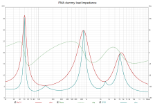
Boden & PMA, we used a large guitar speaker, one of the Celestion G12s IIRC, as a test load for my #138 stability tests. If the unit is unbaffled, (no box) you can usually do this on a test bench comfortably up to more than 100W as the important frequencies appear to be around 100Hz but ear defenders are recommended. The trouble with PMA's load is that it doesn't simulate what happens when you overdrive a big speaker at those frequencies and levels. The load is quite complex, non-linear and non-intuitive.
But the unbaffled woofer impedance and Q would definitely differ from the same driver in the closed or vented box and also cone excursion + inevitable related behaviour is again very different, so you are modelling something that is different from real application of the woofer. I am not sure that it helps to test amplifiers.
I think we are tending off topic into amp design instead of amp assessment. I'm as guilty as others here. But I like to think any assessment would give higher marks to amps which do well in DBLTs 😳
Alas, the tests which show up faults picked up in DBLTs (ie audible faults) are not common or easy to do. eg rise in low level xover dist. when the amp gets stinking hot ... or stability on REAL loads though the latter is better understood these days, ... and overload behaviour
You'll note that these audible faults are mostly very crude once you start looking for them. Nothing like the difference between 0.01% & 0.001% THD.
As for those spruiking current drive (off-topic), NO COMMERCIAL (or other?) SPEAKER is designed for current drive. In another thread, I suggest that if we want these, we need true current drive amps. Buy them from Ye Olde Unobtainium Shoppe 🙂
Yes to all that. But the aim is to excite misbehaviour in an amp. I'll stick my neck out and suggest if an amp passes my test with a big unbaffled unit, it will pass with a close or vented box. Actually around 100Hz, the excursion and related behaviour is almost identical to a closed box and sorta like a vented box too (various caveats apply with my speaker designer hat on. I could design you a box for Celestion G12 where this wasn't the case but it wouldn't be a practical speaker) The big advantage is of course, it's easy to do without annoying your co-workers too much 🙂But the unbaffled woofer impedance and Q would definitely differ from the same driver in the closed or vented box and also cone excursion + inevitable related behaviour is again very different, so you are modelling something that is different from real application of the woofer. I am not sure that it helps to test amplifiers.
Something different than the application of that particular woofer. But it will still exhibit the same range of behaviors as a properly baffled one. Critical frequencies will shift, excursions will become larger. But what happens electrically to the current draw and phase angle will be similar. And it will be 10 dB quieter in the room during the test, and there will be more airflow to cool the woofer.But the unbaffled woofer impedance and Q would definitely differ from the same driver in the closed or vented box and also cone excursion + inevitable related behaviour is again very different, so you are modelling something that is different from real application of the woofer. I am not sure that it helps to test amplifiers.
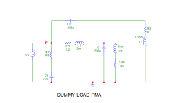
BTW, I use a non-linear, ferrite core inductor in the dummy circuit RLC resonant circuit. Below 100Hz, it is pretty nonlinear and tests damping by creating a divider with amp output nonlinear impedance.The load is quite complex, non-linear and non-intuitive.
In another thread, I suggest that if we want these, we need true current drive amps. Buy them from Ye Olde Unobtainium Shoppe 🙂
Rather build them, it's a DIY forum after all.
Does someone want to propose a dummy load that will test the amplifier’s ability to drive a complex load.
A loudspeaker is not a practical load for reasons of cost and practicability.
A loudspeaker is not a practical load for reasons of cost and practicability.
Last edited:
He wants one, but can't have it until I'm done perfecting mine 😆Rather build them, it's a DIY forum after all.
Magnepan's MG1.6 has an impedance that rises to 19 ohms at 600Hz. It is readily affected by output impedance. An equivalent circuit can be built with resistors instead of the panels.Does someone want to propose a dummy load that will test the amplifier’s ability to drive a complex load.
Ed
Test for asymmetrical crosstalk
Phase coherence across channels with complex waveforms
Test for conducted and radiated EMI/RFI noise incursion. AC line, analog inputs, speaker outputs. Proximity to DECT wireless phone base station (<10ft).
Maybe of some interest: https://scdn.rohde-schwarz.com/ur/pws/dl_downloads/dl_application/00aps_undefined/RCS0702-0032.pdf
Last edited:
Low distortion and high slew rate amplifier are easy to design and it proved by several member in this forum. They all use static signal input.
Dynamic distortion is rare to discuss because it is difficult to measure it. It happened to me like I wrote before. It only just one kind of distortion.
Some kind of dynamic distortion as mention by Dr. Arto Kolinummi are thermal dynamic distortion and power supply and speaker dynamic load distortion.
In subjective things, I want to share my experience when I demonstrated my amplifiers to my friends using their speakers. All my amplifiers have high slew rate but some have high distortion (relative). The high distortion amplifiers seem to sound more pleasing with cheap speakers. Low distortion amplifiers excel with expensive speakers.
I have one amplifier that used by professional sound engineer and speaker designer. They said it have best stereo imaging. But I'm not sure 100% why it have best stereo imaging. It have depth and high.
Very interesting thread.
It wouldn't be too hard to make a spreadsheet where each amp with specs can be entered and then instead of rating them blindly, we provide metrics which the user customizes according to their own tests.
For instance, REW has an SPL log. This can be used to determine the user's loudness needs. The amps can then be sorted according to a metric which weeds out amplifiers which aren't powerful enough.
The ambient noise in the room can be determined with REW and this can be used to sort amplifiers for noise according to the user's speaker sensitivity.
As for amplifier misbehavior, it's not about rating them by misbehavior, it's about eliminating any amplifier that misbehaves. Maybe with some limited allowance for amplifiers that don't misbehave in the conditions in which they will be used.
Slew rate is an overload behavior and a lot of people walk into the trap of using it as an indicator of performance in non-overload conditions. As an amplifier becomes more and more sophisticated, the correlation between overload behavior and behavior during normal listening gets smaller and smaller. So a low slew-rate amplifier can be more linear than a faster amplifier if it is a more sophisticated design. What we care about is the actual listening conditions, and unless the listening test is already a failure, overload behaviors do not represent how the amplifier will behave during listening.
For capacitive load stability, a full test from 1nF to up to 4uF or more really is necessary, a <100Hz tone is good for this, the frequency is low enough it gives oscillation time to build. A really scratchy pot on the signal generator helps too, to trigger any latch/squelch behavior.
For reactive load tolerance, a low frequency is needed to really test this because the thermal time constant of most output transistors is close to 100ms (lower if there is secondary breakdown). A half wave of 100Hz is just 5ms. I think 40Hz is fair since it is close to the statistical peak of the music spectrum.
A simple test would be to choose a resistor and inductor in series which gives the most adverse phase angle for power amp dissipation. The resistor can be lower than the nominal impedance according to some fair statistic of speaker impedances and the inductor chosen for say 60 degrees at a 40Hz test frequency. This is easily combined with the capacitor load stability test. A switch box is convenient but the contact resistance is sometimes enough to hide instability.
Testing using a free air woofer is not necessarily better than a sealed woofer because extreme phase angles cause less strain than moderate phase angles. The woofer peak should be tall and broad so there is more total spectrum taken up by moderate phase.
I think that amplifiers should be rated for minimum DC resistance of the load, with arbitrary series reactance. This is because "nominal" impedance can mean almost anything, and there is no definite worst-case scenario. It just gets more and more absurd. However we can know with certainty that an amplifier can drive a 5ohm resistor no matter what value of capacitance or inductance is in series with that resistor. The amplifier dissipation reaches a maximum somewhere in the vicinity of 50 degrees phase as reactance is added in series with the resistance. This way I can know for certain that an amplifier can drive any speaker with Re=5ohm, unless the crossover was designed with aggressive shunt networks. But there is only so much we can do...
For some background on how reactive power dissipation in an amp breaks down, you can look here: https://www.audiosciencereview.com/...lating-eadr-similar-to-epdr.22019/post-730738
Does someone want to propose a dummy load that will test the amplifier’s ability to drive a complex load.
A loudspeaker is not a practical load for reasons of cost and practicability.
Hi Andrew, I am not sure if to propose, but I can share the circuit I use to test amplifiers (not speaking about trivial R//C):


L2 has non-linear ferrite core, so there is the LF nonlinear effect when measuring distortion at amp terminals


Last edited:
- Home
- Amplifiers
- Solid State
- AFOM: An attempt at an objective assessment of overall amplifier quality