Cyberpup, you sims are so well drawn!
I agree, the diff should go back, especially if you want to drive more than one pair of MOSFETS.
Adding caps to the MOSFETS doesn't really help in any of my sims, what does help slightly is if you drive them with asymmetrical gate resistors instead.
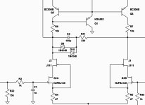
I think the way the BJT cascode was biased is good in that it tracks the JFETs source cancelling some common mode distortion.
Replacing the BJT cascode with high pinch off JFETs does this to more effect with a self biasing arrangement and with less parts as you no longer need the CCS and Zener etc.
I like this self biased cascode and hope it works in real life, it relies on the JFET having quite a negative pinch off voltage so the the Jfe2140 pair has enough voltage to work with.
The only suitable JFETs for the cascode I can find available are J111 and PN4391.
Also, there is decent benefit to adding a current mirror + helper to the IPS.
I tried a couple of different MOSFETS for the current mirror but it didn't work as well as BJTs, I ended up with BC856B as these are available in matched pairs in the form of BCM856D.
With all these changes, the amp sim is south of 1PPM THD until you get beyond 10Khz or so but I haven't spent much time trying to compensate it and by the time this is done properly, THD will surely go up and of course in real life it will be worse still.
Attachments
No.Did you make a new PCB layout for a 100W version with the Hitachi TO-3? 2SK176/J56?
Bobaruni, That is a seriously impressive simulation result!
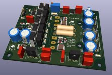
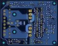
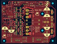
I had already started work on a layout for boards that better utilize the space available in the 2U mini disipante chassis. I was going to add the two op amp servo circuit from Bob Cordell and also a dc detect that will open the output realay if someting goes bad. To make space for these circuits the board will grow to a 70mm width. I will add to the list of changes the parts for the second differential.
I had already started work on a layout for boards that better utilize the space available in the 2U mini disipante chassis. I was going to add the two op amp servo circuit from Bob Cordell and also a dc detect that will open the output realay if someting goes bad. To make space for these circuits the board will grow to a 70mm width. I will add to the list of changes the parts for the second differential.
Thanks Cyberpup but compensation will kill the result, anything that seems to good to be true usually is.Bobaruni, That is a seriously impressive simulation result!
I had already started work on a layout for boards that better utilize the space available in the 2U mini disipante chassis. I was going to add the two op amp servo circuit from Bob Cordell and also a dc detect that will open the output realay if someting goes bad. To make space for these circuits the board will grow to a 70mm width. I will add to the list of changes the parts for the second differential.
I definitely will also build some sort of protection before this thing is connected to any expensive speaker.
I will layout a PCB once the sim is more concrete as I really would like to get some MOSFETs working as the Mirror.
Hi Printnik, Thankyou, I did try the clamp previously and I left it out as it increased THD even with a 10k resistor in series but it still did a good job of preventing the rails from sticking during overload.Hi. Don't forget to add two diodes. Then the clip will be better.
I also tried 2 diodes in series with 10k but still a very slight increase in THD when not clipping at 10KHz.
But you're right, it does need something to make the overload recovery better so I will look at it some more, maybe a diode connected FET will be better.
I spent all day trying to incorporate some way of improving the clipping behavior and everything I tried 2x 1N4148 diodes, 4x diodes, low leakage diodes, diode connected JFETs, diode connected BJTs, combinations of diodes and JFETs, resistors and they all increased THD when not clipping and this contribution scaled with frequency which is why I originally abandoned the idea as I was trying to get the 10-20k THD figure down.Hi. Don't forget to add two diodes. Then the clip will be better.
Then I though about why and realized all of these clamps add capacitance, so adding 2x 1N4148 adds about 8pF to the 100pF compensation cap, when I change this cap to 92pF so that the total capacitance is 100pF again (the value prior to the clamp existing), there is much much less of an impact to THD when the amplifier is not clipping and the clamp actually improves the THD performance slightly around the onset of clipping.
I would use the clamp only if using the current mirror, If you're not using the mirror (AEM6000 and SuzyJ 50W don't use one) then there is no need for clamps as the clipping is already nice and clean.
Bob.
Bobaruni Again, very interesting work! I am now wondering if it is generally true that using a current mirror with a differential pair results in poor clipping behavior? I think Suzyj found this when she added a current mirror to the second stage differentials (her low distortion modifications). I will note that my beloved Yamaha B2 does not have a current mirror on its cascoded FET input stage.
With the current mirror, I think it's a case of the last straw that broke the camels back, I have seen lots of designs that don't misbehave with a mirror so it's probably down to implementation.
Based on sims, the open loop gain on an unmodified SuzyJ 50W is ~100dB, adding the current mirror to this, there is no problem during overload but also not much benefit.
After all the mods, there is ~140dB of gain now which might be too much.
Changing the Input FET to JFE2140 adds about 8dB gain.
Changing the 2nd differential pair to KSA992 and KSC1845 adds about 10dB of open loop gain, this surprised me as that stage has a fixed gain via degeneration but what I think is happening is that the input stage is being loaded much less by the 2nd stage as the Hfe of 992/1845 pairs are ~500 compared to 1381/3503s Hfe of ~150.
The output node at the cascode is high impedance so anything loading it can reduce gain, adding the mirror just adds a few more dB, this might be where the sticking is occurring as the mirror tries to balance the impossibly mismatched currents and gets blamed.
I had a look at the Yamaha B-2, what an interesting design, the MOSFET pairs are driven by separate push-pull emitter followers, the engineers at Yamaha were not afraid to use transistors in the 80s and 90s.
I like that they didn't ruin it by using volume control and input selector ICs, just straight in to a mechanical switch and volume control.
If I make this amp, would it be at all possible to use the 2SK146 as input pairs? Yes, take a laugh befor you answer!
Borbely used the 2SK146 in one of his MC preamps.... so I thought maybe...?
I happen to have a lot of these, and the PCB will be made with "old" through hole components.
Thanks!
🙂 morten
Borbely used the 2SK146 in one of his MC preamps.... so I thought maybe...?
I happen to have a lot of these, and the PCB will be made with "old" through hole components.
Thanks!
🙂 morten
The attached schematic is essentially the original 6000 circuit but with more modern components. The protection circuit monitors the servo output and will trip when it gets close to a rail, indicating too much DC is present. The amp itself simulates very nicely. Perhaps not quite as low a THD value as more significant changes deliver but very respectable (single digit ppm).
Attachments
Could KSC3503 and KSA1381 be replaced with MJE15030 and MJE15031, I know these are a bit overkill in terms of power handling,I have a lot of these lying around and wanted to use them instead of ordering KSC3502/KSA1381 although there is capacitance information published Cib/Cob both are in 100's of PF range and minimum around 50pF but these should be better than MJE340/350 ? Ft is noticably less at 30Mhz also compared to 150Mhz but I guess 30Mhz is also plenty for this application.
I think the short answer is that the MJE15030/MJE15031 could be made to "work" but it would take other design changes to re-compensate the amplifier for the very different high frequency behavior of these parts. After achieving stability, the distortion performance might be disappointing. If you want to pursue it, one approach would be to find the spice models for these parts and load them into LTspice and work out the compensation changes in simulation before an actual hardware build. Hardware that is unstable tends to blow up and it can be difficult to put out the fire. A stable simulation does not guarentee stable hardware, but its unlikely that an unstable simulation would actually work at all.
I have the spice models and will try to simulate it.
Stability wise I think these would be a bit more tame with their lower fT, I am worried about the higher input capacitance which was the reason mentioned for the change from MJE 340/350 . The problem is I can only find KSC3503 with element14 here in India and the complementary is back ordered until like December. Scouring through all the TO126 bjt they had I could not find a suitable equivalent for the 3503/1381.
Stability wise I think these would be a bit more tame with their lower fT, I am worried about the higher input capacitance which was the reason mentioned for the change from MJE 340/350 . The problem is I can only find KSC3503 with element14 here in India and the complementary is back ordered until like December. Scouring through all the TO126 bjt they had I could not find a suitable equivalent for the 3503/1381.
I will post the Kicad files from my layout if anyone wants to modify them for different case sizes. A heatsink may be needed on the drivers depending on where the bias is set. I was planning on running an aluminium bar behind all the devices.
I think the reason I missed these was the TO126N package rather than TO126 with which I filtered on element14, it does not mention Cib however and only mentions Cob. I think speed would be affected by Cib too. These would run a bit cooler though as the continuous collector current is 1A typ/1.5A max.
A bit out of context but where all the western manufacturers seem to be EOLing their traditional fabrication processes Toshiba has come back from dead at least for some of their popular audio BJT's may be the saw the size of the fake/NOS market.
A bit out of context but where all the western manufacturers seem to be EOLing their traditional fabrication processes Toshiba has come back from dead at least for some of their popular audio BJT's may be the saw the size of the fake/NOS market.
Last edited:
In the original article I believe they mentioned BFQ10 up to BFQ16 as a replacement for the ECG461. I don't know which one would be the better subsitute: BFQ10...BFQ16.I have compared all the similar dual monolithic JFETS that can be purchased from Digikey and or Mouser.
Yeah, for sure SST404 gets the closest to the Philips BFQ10 that was specified for use in the original AEM6000.
SST401 is binned to have lower offset voltage and is also available from Digikey so that should be a viable alternative as long as the package is the same.
The LS844 is close to an SST404 but lower offset and noise and less than half the cost 🙂
Also, there is a full datasheet for this whereas I have only seen a brief for most of the other Linear Systems dual JFETs.
But of course the package and pinouts have to be different 🙁
In isolation, the JFE2140 looks great as it has the lowest noise and highest transconductance (which tend to go hand in hand), the downside might be the higher capacitance Ciss and lower breakdown voltage.
I might run some sims to see if the much higher Gfs helps reduce THD but I wonder if too much gain could saturate the IPS?
View attachment 1326792
- Home
- Amplifiers
- Solid State
- AEM6000 Based 50W Amp


