
That looks seriously nice. From my mucking around with the Exicon FETs I found the bias could be happily stable at significantly lower currents than the Hitachi/Renesas ones I’d used. There’s a THD penalty for the lower quiescent current, but it’s not bad.
If you’re keen to play with it, I found substituting KSC3503 and KSA1381 for the MJE340 and 350 transistors in the second stage and VAS was well worthwhile.
If you’re keen to play with it, I found substituting KSC3503 and KSA1381 for the MJE340 and 350 transistors in the second stage and VAS was well worthwhile.
Last edited:
Hi Gunni,
i had built the PCB that was bought from you, and it works and it sounds ok but i can not adjust the quiescent current according to Suzy recommendation which is 100ma per transistor, i have adjusted RV2 to max and the highest i can get is 4.4mV from .22R resistor which is only around 20mA each transistor. any suggestion how to fix the problem?
regards,
mj777
hi mj777
let's find the problem. What voltage to GND are you measuring at R36, R37, respect. R38, R39? Acc. to the suggestion from Suzy, i also would change RV2 to 1k (now 200R). Did you check also R33, R34 and R51-R54 for the correct values? If they are the correct values, your lateral FETs must have a high Ugs threshold voltage
Good luck
Gunni
Hi Gunni,
All good, i manage to adjust the bias to 100mA by changing value of R35 to a higher value as Suzy suggested. Now the amp is singing beautifully.
regards,
mj777
Awesome! Hope you enjoy it - I've just pulled mine out from the main sound system in our loungeroom after about 12 years (my speakers in there now are active two-ways). I did a quick test of noise level and 1 KHz THD and it's exactly the same as when I first built it.
AEM6000 in action 🙂
Hi Suzyj, got it all done, i add a toggle switch, soft start and dc protect on my build. first power up on the amp case hook up with the speakers with nothing connected on it and it is very quiet no hiss or hum. tried playing music using my ipad and it is truly amazing feeling, you can hear the individual instrument playing clear and defined, feels like a live performance. Thanks for a well design pcb and circuit. attached are some pictures of my build. It is an enjoyable experience.
regards,
mj777
Attachments

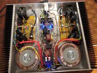

Nice build , Marjohn.
Good to hear, that all works fine.
Crazy, an austrailian designed amp must take a short cut via Germany. I hope the delivered parts were sufficient enough. Enjoy the amp as i do. Actually i work on my layouted PCB of Dadod'S CFA LMOSFET 120W and on the noiseunit amps designed by Suzy. A lot parts to solder😀🙄 to create an active 2way speaker.
BR
Günni
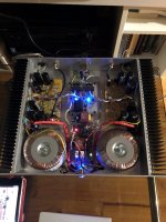
Dunno about the blue leds, but with their exception it looks fantastic. Hope it gives many years of reliable operation.
Excellent build mj777, I have had Günni's boards stashed for ages and this has made me get them out and start building. Thanks to Suzy and Günni for their work.
Can I ask a specific part # for Q1? SST404 seems discontinued, what should I look for in a dual fet?
And what is placed across the power rail pads T6/T7 & T9/T10 - Is this a fuse?
Increase R35 to 330R noted. RV2 is 1k if needed.
Can I ask a specific part # for Q1? SST404 seems discontinued, what should I look for in a dual fet?
And what is placed across the power rail pads T6/T7 & T9/T10 - Is this a fuse?
Increase R35 to 330R noted. RV2 is 1k if needed.
SST404-LF | SST404 Series 50 V 10 mA N-Channel JFET Monolithic Dual - SOIC-8 | CALOGIC
- Future Electronics
T6/T7 & T9/T10 are links - You could also break the links and use a higher supply for the drivers (say +/-56 @ 300VA for the output stage and +/-65 @ 15VA for the drivers) to allow it to drive closer to the rails.
- Future Electronics
T6/T7 & T9/T10 are links - You could also break the links and use a higher supply for the drivers (say +/-56 @ 300VA for the output stage and +/-65 @ 15VA for the drivers) to allow it to drive closer to the rails.
Thanks Suzy, I saw that before but only now see more are in stock very soon.
Seperate supply for the front end is tempting. Maybe with some regulation or a cap multiplier.
Edit... it looks like a VBE already on the front supply rails.
Seperate supply for the front end is tempting. Maybe with some regulation or a cap multiplier.
Edit... it looks like a VBE already on the front supply rails.
Last edited:
Hello friends. My build is plodding along as funds allow. Right now I am planning the transformer specs, hopefully this will be a very nice careful build.
A question, maybe mj777 will pop in - how to resolve the 50V supply 0V on the boards. I initially thought to get 40-0-40V centre tapped secondaries but how will I get the 0V from the bridge rectifier, I can possibly use two full wave rectifiers per channel to get an 0V?
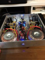
Looking at mj777's build he used a chassis ground to the board 0V, was the transformer secondary simply 0-40V?
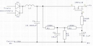
Another plan is to use a separate -/+65V 15VA supply for the front end, as per Suzy's recommendation, with a small cap multiplier for each rail. The PFM Gyrator circuit is one I have used before on a front end supply. Pic below, I may try and make some boards if I can get the hang of Eagle. The Gyrator circuit drops around 4V so will need to spec carefully.
It will be more expensive but I would like to do some matching of BJT's and MJE driver transistors if possible, just to go the distance...
A question, maybe mj777 will pop in - how to resolve the 50V supply 0V on the boards. I initially thought to get 40-0-40V centre tapped secondaries but how will I get the 0V from the bridge rectifier, I can possibly use two full wave rectifiers per channel to get an 0V?
Looking at mj777's build he used a chassis ground to the board 0V, was the transformer secondary simply 0-40V?
Another plan is to use a separate -/+65V 15VA supply for the front end, as per Suzy's recommendation, with a small cap multiplier for each rail. The PFM Gyrator circuit is one I have used before on a front end supply. Pic below, I may try and make some boards if I can get the hang of Eagle. The Gyrator circuit drops around 4V so will need to spec carefully.
It will be more expensive but I would like to do some matching of BJT's and MJE driver transistors if possible, just to go the distance...
Attachments
Suzy, how do you get 65VDC from 9VAC? I'm hoping to get all the windings on a single dual mono transformer.
Would the DC not need a little clean up before the front end? I thought some cap smoothing or regulation would be beneficial.
Would the DC not need a little clean up before the front end? I thought some cap smoothing or regulation would be beneficial.
The 9VAC is rectified and added to the rectified dual 40VAC., so 56V+12ishV = 68V.
There's capacitors on the PCB for both the main supply and the front end supply. You can add additional filtering if you want, but the amp already has fairly good PSRR, so you won't really accomplish much.
There's capacitors on the PCB for both the main supply and the front end supply. You can add additional filtering if you want, but the amp already has fairly good PSRR, so you won't really accomplish much.
Excellent build mj777, I have had Günni's boards stashed for ages and this has made me get them out and start building. Thanks to Suzy and Günni for their work.
Can I ask a specific part # for Q1? SST404 seems discontinued, what should I look for in a dual fet?
And what is placed across the power rail pads T6/T7 & T9/T10 - Is this a fuse?
Increase R35 to 330R noted. RV2 is 1k if needed.
Hi passive420, T6/T7 & T9/T10 i put through hole fuse on it but actually you can just link it with a wire. and im using 40-0-40 AC center tap rectified to have a 56-0-56 DC as illustrated by Suzy on the drawing. one of the best sounding amp i build and enjoyed listening.
regards,
marjohn
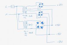
This is what I meant about the +/-65V supplies. The supply for the front end only has to be a little dinky transformer - even 5VA 9V will do:
Hello Suzy,
can the addition of the voltages also be made on the secondaries AC side or do we need the decoupling of the rectifiers ? That means, the main transformer 2x40V AC feed the OPS and the main transformer 2x40V AC + support transformer 2x9V AC feed the frontend.
If necessary, i will post a schematic.
BR
Günni
PS: Still fighting with a practical solution of cooling the OPS of the noiseunit 😕
- Status
- Not open for further replies.
- Home
- Amplifiers
- Solid State
- AEM 6000 ready to build