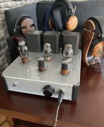
For those of you who don’t want to DIY but want a full production Aegis ready to serve, here you go. Looks gorgeous 😍. The price looks very reasonable and commensurate with the cost of entry and labor.
Best,
Anand.
Best,
Anand.

do you perhaps know how thick they need to be? is it 0.5mm or like 1.6mm?Hello,
I am releasing a DIY tube amplifier project, the first complete DIY project I've released on this forum. The amplifier is called Aegis.
I started my DIY journey on the headphone forum Head-Fi. I have something of a tube DIY blog there where I catalog all of my ongoing projects. For a short period of time, I was building and selling my designs as a hobby business, but quickly realized I didn't have the time for it working a full time job. I thought I'd work on a DIY amplifier that forum members could build for themselves without my involvement. I've been working on it for the past year or so.
This is a headphone enthusiast's tube amplifier. I say that as I'm sure some will balk at the cost of parts, which is roughly $2,000 USD. Given what some people are willing to pay for commercial tube headphone amplifiers, which are creeping toward five figure prices, it's relatively affordable. I tried to come up with a design that 1) is easy to build, even for a novice DIYer, 2) uses easy to acquire vacuum tubes, 3) is simple and robust with low likelihood of parts failure and easy to troubleshoot, 4) uses a circuit that is not readily available on the commercial market, and 5) sounds good! I do not typically build budget-oriented designs for myself, and I did not do so here. I like to build amplifiers that look like professionally made products. Please abstain from telling me that it is too expensive, a waste of money, etc. You do not have to build it.
I've included download links to the BOM, chassis CAD files, and an exhaustive project document that includes an explanation of the circuit, schematics, recommended equipment, information on acquiring parts, step-by-step instructions with photos, testing procedures, and some basic measurements. Please note the instructions are written for a new DIYer, not one with experience, so they are very detailed. The gerber files to order the PCBs are attached to this post.
Measurements are in the last section of the build document.
You can find some subjective impressions of the amplifier here:
https://www.head-fi.org/threads/aegis-diy-tube-headphone-amplifier.965530/post-17224730
https://www.head-fi.org/threads/zmf-caldera-new-planar-magnetic-from-zmf.964836/post-17553801
Please let me know if you come across any typos or anything seems out of place and I will try to address it.
Link to build document PDF: https://drive.google.com/file/d/1C2NSRh8DkC1Blr2GMVC_83XAdM0IUFZA/view?usp=sharing
Link to the Excel BOM: https://docs.google.com/spreadsheet...ouid=113213015624875847507&rtpof=true&sd=true
Link to zipped chassis CAD files: https://drive.google.com/file/d/1GXCq11-S97FtTey2lVpv6CgkBul4Uryb/view?usp=sharing
View attachment 1175520 View attachment 1175523 View attachment 1175525
Hi, If you already seen this over at head-fi, please ignore.
I am trying to create a substitute for the elma switch. My goal is to make something that is easy to build, easy to source and also enables the 600 ohm output from the lundahl transformers. This relay network is what i come up with:


Please give the schematic a look, i don’t have anybody to help me review it before sending to JLCPCB.
Prototype board will arrive next week. If there is interest, i will post the gerber file here once i have verify the design.
I am trying to create a substitute for the elma switch. My goal is to make something that is easy to build, easy to source and also enables the 600 ohm output from the lundahl transformers. This relay network is what i come up with:
- it takes 4 relays to mimic the functionality of the elma switch and 6 to bring out the 600 ohm connection.
- I use a voltage divider on B+ to steal 1 watt @5V to power the relays.
- At rest, it is configured for 32ohm output.
- Connecting SCOM to S1 will switch the output to 150ohm
- Connecting SCOM to S2 will switch the output to 600ohm
- Using a triple throw switch (rotary or toggle) can provide easy switching between all 3 output states.
- I am using this switch for output switching
- I use Omron G6K-2P-Y-DC5 in the design, unit price $4.38USD. This is the relay Woo audio use in the WA23 LUNA for input and output switching.
- The BOM comes to about $40USD and all the parts are readily available everywhere. Well… its just a few resistors, 2 diodes and 6 relays
- The pcb is 71x46mm
Please give the schematic a look, i don’t have anybody to help me review it before sending to JLCPCB.
Prototype board will arrive next week. If there is interest, i will post the gerber file here once i have verify the design.
For those of you who don’t want to DIY but want a full production Aegis ready to serve, here you go. Looks gorgeous 😍. The price looks very reasonable and commensurate with the cost of entry and labor.
Best,
Anand.
It looks gorgeous, but holy sticker shock batman! Does it use gold wires and silver powder capacitors?
I'm unable to start a private conversation, do you still have that spare PCB?I have finished my diy Aegis and have extra pcb if anyone is interested…. Fun project!!
Hi everybody, I'm looking to build an Aegis in the next month or so and started ordering all of parts. Thanks for such a nice build manual and BOM Excel spreadsheet @L0rdGwyn! Unfortunately due to Landfall being closed for the summer I need to source a chassis from somewhere else. I am looking into Front Panel Express and a couple local places. Thanks to help from @Fxfxbones321 I was able to find a beautiful enclosure but I don't have access to a drill press to drill the holes correctly. I am looking for any decent substitutes of places to get the enclosure with holes created. Any assistance is greatly appreciated!
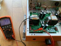
@birusan if the values are different between the two channels, possible there is a short between the pins on the switch PCB somewhere, an easy mistake to make. Not a huge problem and won't affect the amplifier in any detrimental way, but it will cause a channel imbalance. Are the values the same for both channels on the high impedance setting? Can always continue with the build and then if there is a channel imbalance, go back to the switch PCB and hunt down the short, clean it up with some soldering wick.
@L0rdGwyn thank you for the fast reply, surprisingly the values are very close at high impedance setting, both at 4.6 V. Do you think the low impedance values were still setting in upon powering up? Or a short somewhere?
Attachments
Hi, If you already seen this over at head-fi, please ignore.
I am trying to create a substitute for the elma switch. My goal is to make something that is easy to build, easy to source and also enables the 600 ohm output from the lundahl transformers. This relay network is what i come up with:
View attachment 1316359
View attachment 1316360
- it takes 4 relays to mimic the functionality of the elma switch and 6 to bring out the 600 ohm connection.
- I use a voltage divider on B+ to steal 1 watt @5V to power the relays.
- At rest, it is configured for 32ohm output.
- Connecting SCOM to S1 will switch the output to 150ohm
- Connecting SCOM to S2 will switch the output to 600ohm
- Using a triple throw switch (rotary or toggle) can provide easy switching between all 3 output states.
- I am using this switch for output switching
- I use Omron G6K-2P-Y-DC5 in the design, unit price $4.38USD. This is the relay Woo audio use in the WA23 LUNA for input and output switching.
- The BOM comes to about $40USD and all the parts are readily available everywhere. Well… its just a few resistors, 2 diodes and 6 relays
- The pcb is 71x46mm
Please give the schematic a look, i don’t have anybody to help me review it before sending to JLCPCB.
Prototype board will arrive next week. If there is interest, i will post the gerber file here once i have verify the design.
Whatever happened to this idea?
It's mostly done, the relay board itself is working and making all the correct connections. However, I am currently a Pacific Ocean away from my half built Aegis and won't be able to do the final testing until mid-late August when i go back home. (I will finally receive my Lundahl transformers here and carry them back home with me too). Will post the gerber and bom files after final testing.

Last edited:
@L0rdGwyn thank you for the fast reply, surprisingly the values are very close at high impedance setting, both at 4.6 V. Do you think the low impedance values were still setting in upon powering up? Or a short somewhere?
As I already said, it could be a sign of a short. My recommendation is to finish the amp. If you hear a channel imbalance on low impedance, then there is a short, go back and look for it.
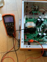
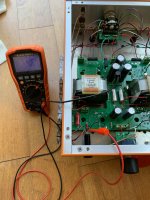
@L0rdGwyn I'm almost to the finish line. Do you think turning the amp over to the side to do testing, and then turning it back right side up - can cause the longer twisted wire soldered to the headphone out jack to flop around a bit and cause some humming noise? Is it from being too close and touch certain areas of the PCB?
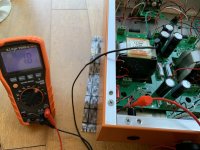
I am at the first testing point. I only have the power tubes right now, they glow fine when turned on but I am getting 0.4 V with no power and then when power goes on it jumps to 0.6-0.7 V. I tried playing with the range but it really is 0.6 volts. I tried measuring the trafo pins and im getting 4.5 V, 4 V, 0.7V and 2.8 V (the last one is the pins that go to the rectifier socket).
Any tips on what to look for to fix this? Thanks.
Any tips on what to look for to fix this? Thanks.
- Home
- Amplifiers
- Tubes / Valves
- Aegis DIY Tube Headphone Amplifier