An externally hosted image should be here but it was not working when we last tested it.
Not very symmetrical...
Nothing wrong with that null. Bob, you're getting very bogged down in detail here. Perfect is the enemy of the good, 'an all that, because it never arrives.
Peerless HDS PPB 830860
Vifa PL14WJ-
SEAS 5INCH
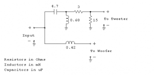
With a 5" Troels usually uses a smaller 1mH bass coil, 10uF resistive damped shunt, and an LCR notch around 1.5kHz. Cross around 3kHz. Otherwise it's the usual circuit, just about 2mH with about 5uF, and an optional tank notch at 7kHz of say 33R and 22uF.
Third order tweeter. You're making it harder than it is.
Peerless HDS PPB 830860
Vifa PL14WJ-
SEAS 5INCH
With a 5" Troels usually uses a smaller 1mH bass coil, 10uF resistive damped shunt, and an LCR notch around 1.5kHz. Cross around 3kHz. Otherwise it's the usual circuit, just about 2mH with about 5uF, and an optional tank notch at 7kHz of say 33R and 22uF.
Third order tweeter. You're making it harder than it is.
This is somewhat true but not entirely. You want a smooth roll-off, but you don't want for example a perfect LR4 slope for both drivers. This has to do with the fact that on a flat baffle there is a path difference between drivers (the sound in the mid originates behind the tweeter). Mild asymmetrical slopes will fix this, see here: Zaph|Audio - ZRT - Revelator Toweryes that is pretty much it you ideally want something approximating a perfect 2nd, 3rd or 4th order slope without too much lumpiness or deviation.
For the OP: put a notch on the breakup, not higher, and a 4KHz crossover point is far too high. I feel that electrical 2nd order on the woofer (+ notch) and 3rd order on the tweeter should work (maybe with a single resistor instead of a L-pad).
Ralf
Tried working with some notch's and changed the tweeter's filter to 3rd order.
Any better?
The tweeter seems to have a flat area around 3.5 KHz, is this breakup as well?
Thanks, Jeremy
Any better?
An externally hosted image should be here but it was not working when we last tested it.
An externally hosted image should be here but it was not working when we last tested it.
An externally hosted image should be here but it was not working when we last tested it.
An externally hosted image should be here but it was not working when we last tested it.
The tweeter seems to have a flat area around 3.5 KHz, is this breakup as well?
Thanks, Jeremy
Jeremy, I keep telling you that you are getting bogged down in detail here.
Little ripples in frequency response are as likely to be diffraction problems as any real audible problem.
Here's a 3kHz XO design with your Vifa D25AG metal tweeter by Marshall Leach. How simple is that?
Vifa 2-Way Loudspeaker System
OK, he's using the classic 6.5" Vifa P17WG polycone, which needs very little filtering beyond a bass coil.
You need to be around 2mH with, say, 5.6uF shunt on the bass. Or you do it better Troels-style on the bass with a smaller 1mH coil, 10uF cap and a LCR notch around 1.5 kHz to get it well-behaved.
Attachments
IMO that last one looks pretty good! You may find the treble a bit hot, but that is pretty easy to adjust 🙂
Tony.
Tony.
Can't seem to get good phase with Marshall Leach's design for the tweeter without changing cap and inductor values.
So if I'm understanding you (Steve) correctly, what's wrong with my previous design is that there are to many components?
If it'll work I'm willing to pay extra for more components than have to wait longer for a better design. With less time spent designing crossovers I can spend more time reading books on crossover design and understand better what you guys are telling me 😛 .
Thanks for all the help, Jeremy
Sorry for jumping in late, and uneducated. 🙂 Here's some tips from what I've seen so far. System7, thanks for mentioning Dr. Leach, I had the chance to audit a class of his in Atlanta long time ago. Taught me most of what I should have remembered about crossover design. 🙂 Seriously, I sucked in that class, but am grateful for what I still retain today. Super nice guy too, he's still missed.
1 - Your FR is a little flat, or up-tilted even for home listening or near-field monitors I think. I would strive for your treble to end around 2-3 db below the 100-200Hz level. Add a small series inductor to the tweeter to adjust the tweeter tilt and adjust the tweeter pad to lower the level a little if needed.
3 - Consider a Zobel on the woofer, not just for the FR, but also, you can cheat with it and adjust it's values to improve phase matching and make accurate slopes easier to achieve. 🙂 Same with any parallel notch filters. You can bump your 0 crossing left or right by nudging the values around. Not sure what you are using, but something like XSim is a great tool for this.
4 - Consider slightly larger 1.8mH inductor to get the woofer pointed the right way as well.
5 - I would say that having a pleasant FR should trump having a 4th order LR aligned top and bottom. That is, sometimes it's easier to get the FR right with 1st on woofer, 3rd on tweeter, especially if you are shaping the woofer's response to have a knee around 1kHz, which I like. Your tastes matter more than what I like though.
6 - Don't sweat phase matching until you have accurate, or at least very close, speaker distances.
Good luck!
Erik
Last edited:
Phase is critical in a crossover because it changes the lobes. This means the response at the listening position and the wall and room interactions. A good crossover will come down to where you decide to put these lobes. Precision is not too critical, as Steve says. The effect is gradual. The physical aspects of a speaker need to have been optimised in order that the crossover can work properly.
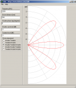
With respect to the lobes below is a post (from a series I've been [very slowly] working on). Not ready for public release as yet 🙂 Have a play with Xdir it's a nice utility.
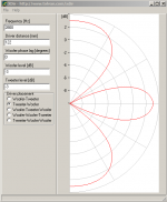
wintermute said:I recently became aware of another tool for simulating vertical polar response. The tool is Xdir Tolvan Data
The simulation is simple but gives a very good idea as to the effects of different placement of speakers on the baffle, how centre to centre spacing affects the polar response, and how phase tracking also affects the polar response.
Below are some images that show the simulated polar response of my own MTM. The first is as it was actually implemented.
You should be able to see from the parameters in the input to the sim the differences. The 5th plot with 90 deg difference between the drivers is interesting!
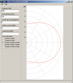
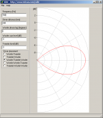
The 6th plot shows an TM implementation to give an idea of the difference between an MTM and TM implementation as far as vertical polar response goes, if "traditional" higher crossover points are being implemented.
Note that when I modeled these I had -3db summing, but my actuall implementation is 4th order bessel accoustic with -6db summing. In reality this only makes a magnitude difference on the graph.
The 7th plot shows the TM with 90 deg phase shift, this demonstrates the often mentioned "tilt"
Attachments


Hey Guys,
I don't really understand why I should be attenuating the tweeter 2-3 db bellow the woofers SPL at 100-200hz. Could you please explain this.
I done some testing with a zobel circuit on the woofer and it was pushing the phase the wrong way(no matter how I changed the values). Also I can't change the notch's component values as it is attenuating the woofer breakup.
With my current box design the centre of the woofer is 136mm away from the centre of the tweeter or 5mm distance between woofer and tweeter frames.
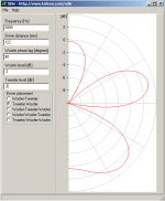
I attenuated the tweeter, changed the woofer filter inductor and cap to 2mh and 5.6uf then played around with xdir.
At xo point
At 8KHz (largest phase difference before woofer drops bellow 40db)
Excuse my Ignorance 😛
Thanks, Jeremy
I don't really understand why I should be attenuating the tweeter 2-3 db bellow the woofers SPL at 100-200hz. Could you please explain this.
I done some testing with a zobel circuit on the woofer and it was pushing the phase the wrong way(no matter how I changed the values). Also I can't change the notch's component values as it is attenuating the woofer breakup.
With my current box design the centre of the woofer is 136mm away from the centre of the tweeter or 5mm distance between woofer and tweeter frames.
I attenuated the tweeter, changed the woofer filter inductor and cap to 2mh and 5.6uf then played around with xdir.
An externally hosted image should be here but it was not working when we last tested it.
An externally hosted image should be here but it was not working when we last tested it.
An externally hosted image should be here but it was not working when we last tested it.
At xo point
An externally hosted image should be here but it was not working when we last tested it.
At 8KHz (largest phase difference before woofer drops bellow 40db)
An externally hosted image should be here but it was not working when we last tested it.
Excuse my Ignorance 😛
Thanks, Jeremy
Hey Guys,
I don't really understand why I should be attenuating the tweeter 2-3 db bellow the woofers SPL at 100-200hz. Could you please explain this.
While not a strict requirement, I find you end up with a neutral and musical sounding speaker this way. Perfectly flat speakers to me sound very dry.
I think there's also something to do with direct vs. reflected energy at the higher frequencies. You end up with more energy in that region due to reflections, which reducing the level a little compensates for. It's basically the difference between listening to a flat speaker in an anechoic chamber vs. a real living room, but I'm sure I've only got it half right.
I will say that's how I've tuned my current pair and couldn't be happier.
Best,
Erik
With little cabinet stuffing and a 4.7 ohm resistor on the tweeter the tweeter is on average 2db lower than the woofer at 150hz.
With more cabinet stuffing and a 3 ohm resistor on the tweeter the response is flat +- 2db down to 70hz.
Phase for both are pretty much identical and the same as last post.
This way I can buy an extra couple of resistors and a bunch of wool to tune the speakers to sound best in my room. Is there anything wrong with this idea and/or crossover?
Thanks, Jeremy
An externally hosted image should be here but it was not working when we last tested it.
An externally hosted image should be here but it was not working when we last tested it.
With more cabinet stuffing and a 3 ohm resistor on the tweeter the response is flat +- 2db down to 70hz.
An externally hosted image should be here but it was not working when we last tested it.
An externally hosted image should be here but it was not working when we last tested it.
Phase for both are pretty much identical and the same as last post.
This way I can buy an extra couple of resistors and a bunch of wool to tune the speakers to sound best in my room. Is there anything wrong with this idea and/or crossover?
Thanks, Jeremy
With
This way I can buy an extra couple of resistors and a bunch of wool to tune the speakers to sound best in my room. Is there anything wrong with this idea and/or crossover?
Thanks, Jeremy
Jeremy,
Not at all. Being able to tune your speakers to your room and your tastes is one of the major justifications/excuses/explanations for building your own speakers.
Besides, for all of us, tying together design, simulation, fabrication and testing is a learning experience that cannot be substituted by theory alone. Every time you go through the process of making a change, measuring the difference and evaluating the aesthetic result you gain huge amounts of knowledge about the technology and yourself that cannot be gleaned any other way.
As for the crossover, you are probably OK with the small resistor changes. You don't have to post here, but double check the inverted tweeter chart just to be confident you'll still get good phase matching with either resistor. It may now be time to check your resistor wattages if you haven't already though. 🙂
Best,
Erik
Last edited:
I also want to point out, not enough commercial "high end" (and I use the term with derision) speaker makers go through the trouble of evaluating, let alone designing, speakers for the average buyer's home. If you have the opportunity to evaluate and optimize your speakers for your listening room it puts you ahead of 90% of the commercial speaker makers.
Best,
Erik
Best,
Erik
The reverse null graphs look fine to me. 😛
" It may now be time to check your resistor wattages if you haven't already though."
How do I work this out?
Thanks, Jeremy
" It may now be time to check your resistor wattages if you haven't already though."
How do I work this out?
Thanks, Jeremy
Build it, run at 200 watts overnight, come back and see what smoked... 🙂
Not sure about other tools. In XSim there is actually a wattage chart for each component. Remember that your tweeter wont' get more than 20% of the power, so it's save to evaluate the woofer at 100 Watts and the tweeter at 20 for 100 Watts power handling.
Best,
Erik
Not sure about other tools. In XSim there is actually a wattage chart for each component. Remember that your tweeter wont' get more than 20% of the power, so it's save to evaluate the woofer at 100 Watts and the tweeter at 20 for 100 Watts power handling.
Best,
Erik
Normally you'd play some music then go and feel them, but yes xsim does have this neat feature. I'd expect little direct correlation between calculated values and playing music but they'd probably be overestimated anyway. I'd still check by feel.
Normally you'd play some music then go and feel them, but yes xsim does have this neat feature. I'd expect little direct correlation between calculated values and playing music but they'd probably be overestimated anyway. I'd still check by feel.
I'm not sure how well you or anyone can correlate feeling with power, or how close the resistors might be to their limits.
Best,
Erik
- Status
- Not open for further replies.
- Home
- Loudspeakers
- Multi-Way
- Advice on bookshelf speaker build