Can you confirm this with real measurements of your designs?
Besides, the crossover of these small monitors has no baffle step compensation, it is too simple to talk about correct filtering of the speakers.
Those schematics you showed are book examples of theoretical filters that were not built based on real and correct acoustic measurements.
😆 😆 😆
No, these are real examples, built and tested :
Thank you, I know how to make correct acoustic measurements :
I am also able to recognize by ear when a speaker is in phase or not, and if the transients match themselves between the speakers or not. No need to simulate, nor ot measure it...
I do not have measurements of my designs because for now, my measurement chain has become obsolete (thank you Windows).
T

If you took measurements in the way you showed in the pictures, then unfortunately it is not about the correct way.Thank you, I know how to make correct acoustic measurements :
Don't get me wrong. I also like to use series crossovers, but what you have shown will not work correctly.
I encourage you to re-do the measurements one day according to generally known guidelines.
It really depends on the order of rolloff, not the electrical slope, and I've had them line up both ways on different designs. It is not just because they are SXO filters.
It really depends on the order of rolloff, not the electrical slope, and I've had them line up both ways on different designs. It is not just because they are SXO filters.
Yes. In essence, for the S- // Xover, the order of the rolloff starts at circa 3dB at the crossing frequency, increases to 6dB, then 9dB, and approaches slowly 12dB at the end. Here are two simulations made by an Audio friend and presented on his webpage (250Hz / 4kHz) :
* A 3-ways classic parallel 6dB/Oct. crossover shows the regular slopes at 6dB per octave :
* A 3-ways serial-parallel 1st order crossover shows the increasing slopes :
* Note that the speakers on the diagram above are all in same polarity, hence the synchronized transient response between speakers, shown below on square waves, by the serial-parallel configuration :
That said, the speakers must be linear enough around the crossing frequencies (2 octaves would be the ideal) : no great accident in the response nor in the impedance curves, like for a classic // 6dB/Oct. by the way, but fortunately in a lesser extent for that S-// configuration.
T
Last edited:
The very first post in this thread shows a real world example where a polarity inversion is required. 🙂Unfortunately, in the real world, that doesn't work like this in a 1st order serie crossover, being in 2 or 3 ways, or over : any polarity inversion is heard as a scooped mid tone, and the transient response is erased. You guess that I made the test several times on several enclosure projects, and each time : same conclusion...
Dave.
Yes you certainly can.Very interesting discussion. If one designed a two way 1st order series crossover for woofer and wide band (FR) could one add a helper tweeter/super tweeter by simply paralleling a cap blocked tweeter or would a redesign as a three way be necessary?
I have just obtained a pair of Pioneer B350PRO bullet super-tweeters for a very similar reason.
Their very high efficiency and 'natural bandwidth' means you can bring them into SPL range
using a single low value capacitor, achieving attenuation & very high frequency output simply.
However, you must get your (+/- ) phase polarity correct for proper results.
Hello all,
Some posts ago I read > "These are standard 'book shelf' crossover networks, without compensation for "baffle step".
I would like 1, 2 or more members to present 2 examples of: *1. basic XO and then *2. XO with baffle step compensation.
I would be very interested to see some examples of this 🙂
Some posts ago I read > "These are standard 'book shelf' crossover networks, without compensation for "baffle step".
I would like 1, 2 or more members to present 2 examples of: *1. basic XO and then *2. XO with baffle step compensation.
I would be very interested to see some examples of this 🙂
Your .frd or .txt and .zma measurement files are simple text files in columns and can survive fully independently from MS-DOS 3.1 or whatever until Win11.I do not have measurements of my designs because for now, my measurement chain has become obsolete (thank you Windows).
Your .frd or .txt and .zma measurement files are simple text files in columns and can survive fully independently from MS-DOS 3.1 or whatever until Win11.
Yes. But I don't have them anymore - I even wonder if I had them. I just have the proprietary application files.
Now I have a ARTA license, and some other free software, but the perspective of reinstating a complete measurement chain makes me lazy. 🙁
T
https://www.diyaudio.com/community/...overs-without-measurement.189847/post-6910468I would like 1, 2 or more members to present 2 examples of: *1. basic XO and then *2. XO with baffle step compensation.
I would be very interested to see some examples of this 🙂
Hello all,
Some posts ago I read > "These are standard 'book shelf' crossover networks, without compensation for "baffle step".
I would like 1, 2 or more members to present 2 examples of: *1. basic XO and then *2. XO with baffle step compensation.
I would be very interested to see some examples of this 🙂
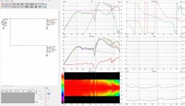
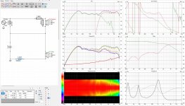
I will show such an example of filtration based on my design of a cheap stand monitor, in which I used a series crossover. In the next few posts I will describe its behavior. Measurements for the crossover were taken using Arta software, on a 0 to 90 degree rotary table.
The first screenshot is the measurements of the speakers connected in parallel. As you can see, this is a connection in the same polarity, and even without any crossover we see quite a bit of phase distortion.
Attachments
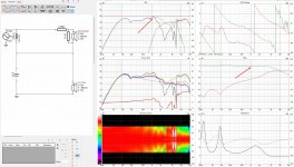
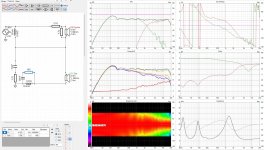
Now let's see how the simplest 1st order serial crossover works. I added an Lpad for the tweeter to the schematic to lower its SPL slightly relative to the midwoofer.
Looking at the transmittance of the filter, you can see that such a crossover is unable to correct the Baffle step phenomenon that occurs with a typical loudspeaker enclosure. If we used an infinite baffle for these speakers, such a simple filter could work, but in the real world we still have a problem with the midwoofer, whose frequency response is not ideal and requires further intervention.
The two speakers are still connected in the same polarity, which manifests itself in a huge frequency response hole caused by a phase mismatch.
Reversing the polarity of the tweeter significantly improves the frequency response.
Attachments
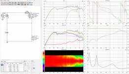
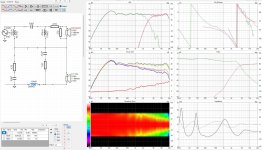
We need to add another coil to our schematic to correct the Baffle step effect. This is still far from the theoretical ideal, especially considering the frequency response of the midwoofer. We need to attenuate the break up of the cone, which can be achieved by using additional elements at our coil responsible for Baffle step correction. This is a typical LCR scheme, acting as a notch filter. I have added a series resistor to the schematic, which will make it easier to achieve optimal filtering characteristics and impedance without large drops in the higher bandwidth.
In the end, we have a series crossover with a small number of elements, but allowing for effective speaker filtering. This crossover scheme is quite versatile and even when using speakers with not very even frequency response, one can get quite good results.
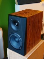
Thanks to the use of a waveguide tweeter and an enclosure with chamfered sides, we get fairly even bandwidths off the listening axis. The waveguide also allows for better time alignment of the speakers.
In the end, we have a series crossover with a small number of elements, but allowing for effective speaker filtering. This crossover scheme is quite versatile and even when using speakers with not very even frequency response, one can get quite good results.
Thanks to the use of a waveguide tweeter and an enclosure with chamfered sides, we get fairly even bandwidths off the listening axis. The waveguide also allows for better time alignment of the speakers.
Attachments
Maybe a little OT, but ...
I´ve been using the S- filter in the attachment in several 6,5 inch + tweeter constructions and been satisfied with the results.
But I don´t fully understand how the 6,8 uF capacitor and 2,2 ohm resistor attached between the two capacitors and the + terminal of the B/M works.
Has anyone an explanation?
Attachments
@rolf101
Yeah, that's been discussed here on the forum previously.
It's sort of an "in-between" configuration for series-crossover advocates that can't fully commit.
The 2.2 ohm resistor would be a wire in a series crossover. But if you were to raise the value high enough you'd have a parallel crossover.
Dave.
Many thanks Dave,
Of course I should have seen the shorted 2,2 ohm resistor as a vital part of the series X0.
But I still don´t understand the 6,8 capacitor and how to use it use it together with the resistor when I alter the XO.
Anyhow, I find it easy to use and I find it satisfactory.
Of course I should have seen the shorted 2,2 ohm resistor as a vital part of the series X0.
But I still don´t understand the 6,8 capacitor and how to use it use it together with the resistor when I alter the XO.
Anyhow, I find it easy to use and I find it satisfactory.
Here, a detailed simulation of a couple of systems I built using series subwoofer crossovers.
Example #1, Subwoofer #1:
Subwoofer: TangBand W5-1138SMF in a 14 liter reflex enclosure tuned to 36Hz. 2" port.
Satellite: JVC HSA1014 (4") and Dayton ND16FA (0.625") in a 1 liter sealed box. Tiny little speakers.

The crossover is a super-simple SERIES circuit with 2 elements: 7mH inductor in parallel with the satellites + 250uF cap in parallel with the sub, and those two circuits wired in series - as shown here:

The filter curves (right side middle row) show that the sub drive signal is roughly a 6dB slope with impedance interactions working in your favor. (They work against you in parallel circuits, as discussed earlier in this thread.) The two impedance peaks from the sub, at 30Hz and 52Hz, suppress output in the satellites at those frequencies - which is ideal. The single impedance peak from the satellite, at 180Hz, suppresses output from the sub at that frequency.
The satellite drive signal is roughly a 2nd order shelf filter with -16dB asymptote and a pretty steep drop below 100Hz which is exactly what we want.
I get the best results wiring with normal polarity on both sub and satellite.
I also modeled them as being separated by 1 meter and the directivity graph lower left gives you some idea about interference patterns.
Example #1, Subwoofer #2:
I switch out the 5" sub for a TangBand 8" W8-740P subwoofer with 10" passive radiator in a 20 liter box.

I get this result:

As you can see the sub has impedance peaks at 22Hz and 40Hz, which are reflected as dips in the satellite drive signal at those points. Signal rapidly falls below 70Hz. This is desirable.
These measurements are from the actual speakers in my room, nearfield, as best I can manage. No attempt has been made to gate out room reflections.
Example #2, Subwoofer #1:
Then I switched in these satellites, which are 7 liter bass reflex design with a TangBand W4-654S woofer and Audax TW025A0 dome tweeter:

Here is the VituixCad simulation using the actual SPL and impedance measurements for TB 5 sub and satellite:

Example #2, Subwoofer #2:
And below is the same ported satellite with the 8" sub.

Both of these subs are ported so they have an upper impedance peak at either 40Hz (8" sub) or 52Hz (5" sub) and those assist in making the satellite rolloff steeper. A sealed sub would only have one impedance peak at Fb.
This simple series circuit 7mH / 250uF would be an effective 100Hz crossover for many subwoofer / satellite combinations, and 90% of the time will work much better than a standard parallel circuit.
Comment on the (approximately) 6dB low pass filtering of the sub:
Intuition might suggest that if you want a sub to "disappear" and blend well with the satellites, you need to use steep crossover slopes. This would minimize the overlap between subs and sats; so it seems like that would make the subwoofer's position less obvious. It would also make for fewer comb filtering effects and less interference.
On paper, the above would seem to be obviously true.
In reality, I've found the opposite to be true. I've found that if the subwoofer has a gradual downward slope, it calls less attention to itself and blends better with the satellites. The 6dB slope has less phase shift.
I've found that the steeper the subwoofer/satellite crossover, the more the subwoofer sounds like a separate, disembodied entity. That's why I prefer shallow slopes. I say this having done all manner of exotic experiments with DSP etc., not just passive crossovers.
I've also found that unless your satellites have plenty of bass capability, the #1 priority is removing bass load from the satellites so they're not strained. This makes them sound much better. That calls for a steeper filter between 50-100Hz than 6dB. This is precisely why I like series crossovers so much, because the impedance peaks of the sub steepens the satellite slope.
I also think that a low shelf filter (which you get from this kind of series crossover) with an asymptote of 15-20dB is enough to do the job. It reduces excursion by 75-80%. You don't need more attenuation than that, and the shelf filter also has half the phase shift that a standard 12dB filter would have. The reduced phase shift also helps the subs and satellite blend.
The LF asymptote is determined by the DCR of the inductor in parallel with the satellites.
Here I use a 7mH inductor with 1 ohm DCR and that gets me about 16dB attenuation. Lower DCR will reduce LF signal to the satellites even more; Higher DCR will bleed more LF into the satellites.
You can calculate the LF asymptote: dB = 20 * Log ((Inductor DCR)/(Satellite DCR))
Example #1, Subwoofer #1:
Subwoofer: TangBand W5-1138SMF in a 14 liter reflex enclosure tuned to 36Hz. 2" port.
Satellite: JVC HSA1014 (4") and Dayton ND16FA (0.625") in a 1 liter sealed box. Tiny little speakers.
The crossover is a super-simple SERIES circuit with 2 elements: 7mH inductor in parallel with the satellites + 250uF cap in parallel with the sub, and those two circuits wired in series - as shown here:
The filter curves (right side middle row) show that the sub drive signal is roughly a 6dB slope with impedance interactions working in your favor. (They work against you in parallel circuits, as discussed earlier in this thread.) The two impedance peaks from the sub, at 30Hz and 52Hz, suppress output in the satellites at those frequencies - which is ideal. The single impedance peak from the satellite, at 180Hz, suppresses output from the sub at that frequency.
The satellite drive signal is roughly a 2nd order shelf filter with -16dB asymptote and a pretty steep drop below 100Hz which is exactly what we want.
I get the best results wiring with normal polarity on both sub and satellite.
I also modeled them as being separated by 1 meter and the directivity graph lower left gives you some idea about interference patterns.
Example #1, Subwoofer #2:
I switch out the 5" sub for a TangBand 8" W8-740P subwoofer with 10" passive radiator in a 20 liter box.
I get this result:
As you can see the sub has impedance peaks at 22Hz and 40Hz, which are reflected as dips in the satellite drive signal at those points. Signal rapidly falls below 70Hz. This is desirable.
These measurements are from the actual speakers in my room, nearfield, as best I can manage. No attempt has been made to gate out room reflections.
Example #2, Subwoofer #1:
Then I switched in these satellites, which are 7 liter bass reflex design with a TangBand W4-654S woofer and Audax TW025A0 dome tweeter:
Here is the VituixCad simulation using the actual SPL and impedance measurements for TB 5 sub and satellite:
Example #2, Subwoofer #2:
And below is the same ported satellite with the 8" sub.
Both of these subs are ported so they have an upper impedance peak at either 40Hz (8" sub) or 52Hz (5" sub) and those assist in making the satellite rolloff steeper. A sealed sub would only have one impedance peak at Fb.
This simple series circuit 7mH / 250uF would be an effective 100Hz crossover for many subwoofer / satellite combinations, and 90% of the time will work much better than a standard parallel circuit.
Comment on the (approximately) 6dB low pass filtering of the sub:
Intuition might suggest that if you want a sub to "disappear" and blend well with the satellites, you need to use steep crossover slopes. This would minimize the overlap between subs and sats; so it seems like that would make the subwoofer's position less obvious. It would also make for fewer comb filtering effects and less interference.
On paper, the above would seem to be obviously true.
In reality, I've found the opposite to be true. I've found that if the subwoofer has a gradual downward slope, it calls less attention to itself and blends better with the satellites. The 6dB slope has less phase shift.
I've found that the steeper the subwoofer/satellite crossover, the more the subwoofer sounds like a separate, disembodied entity. That's why I prefer shallow slopes. I say this having done all manner of exotic experiments with DSP etc., not just passive crossovers.
I've also found that unless your satellites have plenty of bass capability, the #1 priority is removing bass load from the satellites so they're not strained. This makes them sound much better. That calls for a steeper filter between 50-100Hz than 6dB. This is precisely why I like series crossovers so much, because the impedance peaks of the sub steepens the satellite slope.
I also think that a low shelf filter (which you get from this kind of series crossover) with an asymptote of 15-20dB is enough to do the job. It reduces excursion by 75-80%. You don't need more attenuation than that, and the shelf filter also has half the phase shift that a standard 12dB filter would have. The reduced phase shift also helps the subs and satellite blend.
The LF asymptote is determined by the DCR of the inductor in parallel with the satellites.
Here I use a 7mH inductor with 1 ohm DCR and that gets me about 16dB attenuation. Lower DCR will reduce LF signal to the satellites even more; Higher DCR will bleed more LF into the satellites.
You can calculate the LF asymptote: dB = 20 * Log ((Inductor DCR)/(Satellite DCR))
Last edited:
For reference, these are the impedance curves and frequency response curves used in the VituixCad simulation. All these were measured in my room so curves include floor and wall reflections; subwoofer measurements are ground plane, not nearfield.
TB 5" ported Subwoofer:

TB 8" Ported Subwoofer:

JVC micro satellites 1 liter sealed box:

Tang Band W4-654S + Audax 1" 7 liter ported box:

TB 5" ported Subwoofer:
TB 8" Ported Subwoofer:
JVC micro satellites 1 liter sealed box:
Tang Band W4-654S + Audax 1" 7 liter ported box:
- Home
- Loudspeakers
- Multi-Way
- Advantages of Series Crossover vs Parallel for Subs & Open Baffle