I was extremely unlucky. I bought two new units. One had a problem with the HF part, the other one with the MF part. O returned them under warranty and I am waiting to have them fixed.B&C's FB4648 dedicated passive crossover for the DCX462 and DCX464 8 ohm HF coaxial drivers appears to work fine in their measurements, the polarity of the HF is reversed, "a huge wide dip" would result if it wasn't.
Quite surprised that happened with their QC......
What's the problem you faced?
The frequency response off very much on both drivers?
What's the problem you faced?
The frequency response off very much on both drivers?

I remembered someone on diyaudio also face the HF frequency response issue.
After the examination there's some glue left in the HF coil gap at that case.
Luckily mine are okay...I bought from abroad and it'll be painful if repair is needed for me...
Edit: this thread
https://www.diyaudio.com/community/threads/dcx464-busted-5db-difference-in-hf.368946/
After the examination there's some glue left in the HF coil gap at that case.
Luckily mine are okay...I bought from abroad and it'll be painful if repair is needed for me...
Edit: this thread
https://www.diyaudio.com/community/threads/dcx464-busted-5db-difference-in-hf.368946/
You can but why would you do that?
And let's clarify from the start, here we are talking about 1st order series xo, not 2nd, not 3rd.
There is a huge difference and I would recommend reading Rod Elliott's articles on the topic:
https://sound-au.com/parallel-series.htm
https://sound-au.com/articles/6db-xover.htm#s3
1st order series xo does not need either Zobels or notch filters as the very nature of the filter takes care of all this.
The issue usually comes down to careful selection of drivers.
If you insist on using such networks you'll be better off with a parallel filter.
Ignore the parallel filter crowd who'll tell you parallel and series filters are the same and you can use the same techniques in both and achieve the same result. That's rubbish.
Those people crave control in the belief that somehow it will produce a better sounding speaker.
Ever thought why the resurgence in popularity of Full Range drivers and single driver speakers?
Many reasons but an important one is because they sound natural.
A 1st order series filter with carefully selected drivers creates sort of a quasi-full range speaker. It is not the same but comes very close.
We can keep talking and I'm sure this discussion will continue but all it takes is a Open baffle of some sort because it's simple, two drivers, a woofer and a small full range like Vifa, TB, or the more expensive Mark Audio, an inductor and a capacitor with values calculated for your xo point and maybe a resistor or two for level balancing.
Wire it up, measure the impedance to be sure you won't stress your amp, fire it up and listen.
Later if you like the result play with XSim and/or VituixCAD, optimise it and listen again.
BTW, the late John Dunlavy used to evaluate his speakers with square wave signals. As it's known 1st order filters are the only filters that can reproduce a square wave relatively well. Of course Mr. Dunlavy was using quite complex 1st order filters trying to produce the perfect phase coherent speaker.
Now try the same exercise with a series one (6dB) and be amazed.
Yes @Stanislav : I agree.
After many experimentations and listening comparisons with 6dB/Oct. // and 12dB/Oct. // configurations, I'll even add some other advantages to the serial 6dB/Oct. crossover :
1 - the speakers are connected in same polarity. This means that on a transient wave, the cones will move in the same direction, without any other delay than the construction flaws of each speaker can provide, unlike on most higher order crossovers.
2 - the speakers are in Serie, and connected directly to the amplifier's terminals, without passing through a LC crossover component (wired in // to the speakers). This means that no possible phase gap or rotation exists than the construction flaws of each speaker can provide.
3 - the number of parts are minimalistic. This simplicity means that the insertion losses are reduced, and as they are not in serie with the speakers, they possibly have less impact on efficiency.
4 - each speaker "sees" the same LC assembly, conversely to the // 6dB/Oct. configuration, where each speaker "sees" a L or a C. A parallel 12dB/Oct. offers also a LC assembly, so it may be an explanation for the attenuation slopes of the Serie 6dB/Oct. closer to a 2nd order slope.
All my DIY speakers have now 6dB/Oct. Serie crossover, being 2-ways or 3-ways. I even went for this solution when I rebuilt the crossovers of my Magnepan SMGb. The results are amazing and at any rate, I wouldn't go back !
T
And have you measured whether the actual acoustic roll off is 6dB/Octave?All my DIY speakers have now 6dB/Oct. Serie crossover, being 2-ways or 3-ways. I even went for this solution when I rebuilt the crossovers of my Magnepan SMGb. The results are amazing and at any rate, I wouldn't go back !
And have you measured whether the actual acoustic roll off is 6dB/Octave?
No, because I do not have the instruments to do this anymore (obsolete software, thank you Windows).
I think that the slope is between 6dB/Oct. and 12dB/Oct, if I rely on several (but few) studies I read on the subject (including those mentioned by @Stanislav in his post). I can mention others, but these are in French :
http://jimbee.over-blog.com/page-5371974.html
https://www.audiotechno.fr/php/filtre-serie.php
T
The issue is that these 6dB and quasi 6dB electric slopes once loaded with a real driver rather behave like acoustic second or third order slopes.
... which is why they are useful: 1st-order advantages plus the necessary, effectively higher-order slope. I tweak the LP and HP frequencies (calculated for parallel) somewhat past each other to avoid a dip. Cannot this be sim'ed?
No: the -claimed- advantages are no longer there as soon is the slope is no longer 1st-order. Any decent simulator can sim parallel networks.1st-order advantages
I use only 6dB Series filters in all my builds and this is exactly the behavior I see.
I know people are hesitant using Series XO, especially 1st order, because they think they lose the imaginary control of the parallel filters. Actually it is exactly the opposite, the simplicity and elegance of the 6db Series XO makes life so much easier as Perry and Allen explained above.
Try it in practice and see for yourself.
Interesting. I hope I don't get thread sidetracked, but what kind of rules is involved in this first-order series filter when thinking about the distances/ C to C between the drivers? Was it that all first order filters (parallel or series) require very short/shorter than usual distances to work properly? For example, If using Mabat´s Exar 400 horn and instead using steep filters at approx 700Hz would it be worth to try with first order series filter? C-to-C would be huge if using 15" ..
Last edited:
Above re: 1st-order series.
Someone please sim 1st-series vs 1st-parallel vs 2nd-parallel, including phase. Thanks.
Someone please sim 1st-series vs 1st-parallel vs 2nd-parallel, including phase. Thanks.
Last edited:
Same rules as for any other slope or order.Interesting. I hope I don't get thread sidetracked, but what kind of rules is involved in this first-order series filter when thinking about the distances/ C to C between the drivers? Was it that all first order filters (parallel or series) require very short/shorter than usual distances to work properly? For example, If using Mabat´s Exar 400 horn and instead using steep filters at approx 700Hz would it be worth to try with first order series filter? C-to-C would be huge if using 15" ..
C to C ideally should by 1/4 wavelength of the XO frequency, in many cases not possible.
I have a pair of OB speakers with a 15" woof crossed at around 250 - 300 Hz, followed by an 8" FR (SB20). The C-C distance is roughly 35cm.
So 344/300=1.146m, this is the wavelength.
1.146/4=0.28m, just about right.
In my case a smaller FR will help.
You can't simulate these in any of the free crossover design packages yourself?Someone please sim 1st-series vs 1st-parallel vs 2nd-parallel, including phase. Thanks.
Attached. This is assuming a purely resistive 8ohm electrical load, flat FR, phase & coincident acoustic centres (so we're just looking at the electrical transfer functions: the second you apply real-world drivers to this, with their frequency-varying impedance loads, variable frequency/amplitude responses & offsets between the drivers in the 3-planes it all goes to pieces).
1st order parallel, 1st order series, 2nd order Butterworth & LR2 shown with a 1KHz nominal frequency. I included two different 2nd order filters since you didn't specify any particular type -in this case Butterworth for type-consistency & LR2 because it electrically speaking sums flat. The 2nd order filters both have the HF polarity flipped as they are 180 degrees out of phase in the same polarity. 1st order sums with 90 degrees phase difference, whether it's a series or parallel filter. No mysteries here. With a purely resistive electrical load & ignoring everything else, 1st order series & parallel are identical in terms of the summed / system impedance, frequency response & phase shift. It's when you get to real-world applications that you can start to see functional differences -but for that, we'd need to have the measured FR, phase & impedance data for a given speaker.
Attachments
Last edited:
Same rules as for any other slope or order.
C to C ideally should by 1/4 wavelength of the XO frequency, in many cases not possible.
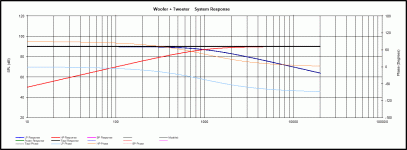
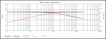
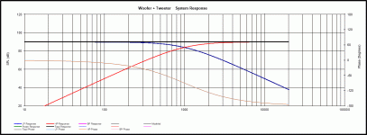
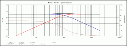
Yes, that's it. I did my best to achieve that on my 375L Monitors (DIY) - and yes, this is not always possible... Here, FC are 5000Hz and 400Hz.
Below, at left, the 12dB/Oct. // version ; at right, the 6dB/Oct. Serie version - both listening-tested on the speakers above, in instant A/B test, with the same sources / amps / musical program and samples :
No picture : the 6dB/Oct. Serie configuration completely buries the 12dB/Oct. // configuration above, aurally speaking.
Stanislav said:
I use only 6dB Series filters in all my builds and this is exactly the behavior I see.
I know people are hesitant using Series XO, especially 1st order, because they think they lose the imaginary control of the parallel filters. Actually it is exactly the opposite, the simplicity and elegance of the 6db Series XO makes life so much easier as Perry and Allen explained above.
Try it in practice and see for yourself.
Yes. If we did not tested it - as objectively and seriously as possible - with Audio friends, we would never have believed it ! Like what, as often, la carte n'est pas le terrain ( the map is not the terrain)...
T
THANKS Scott. But I already knew the simplistic story of this four-way comp and it does not show/explain features such as slope and phase of 1st-order series vs the rest. Hence my request (even begging) for the difference to be sim'ed, if only for a "typical" or ideal set of drivers (impedance curves, phase) and test conditions (baffle layout, aligned acoustic centers, etc).You can't simulate these in any of the free crossover design packages yourself?
Attached. This is assuming a purely resistive 8ohm electrical load, flat FR, phase & coincident acoustic centres (so we're just looking at the electrical transfer functions: the second you apply real-world drivers to this, with their frequency-varying impedance loads, variable frequency/amplitude responses & offsets between the drivers in the 3-planes it all goes to pieces).
1st order parallel, 1st order series, 2nd order Butterworth & LR2 shown with a 1KHz nominal frequency. I included two different 2nd order filters since you didn't specify any particular type -in this case Butterworth for type-consistency & LR2 because it electrically speaking sums flat. The 2nd order filters both have the HF polarity flipped as they are 180 degrees out of phase in the same polarity. 1st order sums with 90 degrees phase difference, whether it's a series or parallel filter. No mysteries here. With a purely resistive electrical load & ignoring everything else, 1st order series & parallel are identical in terms of the summed / system impedance, frequency response & phase shift. It's when you get to real-world applications that you can start to see functional differences -but for that, we'd need to have the measured FR, phase & impedance data for a given speaker.
May I also propose a "null hypothesis" experiment: take two identical drivers, near-flat impedance area, crossover one to the other. Should be zero audible difference series vs parallel 1st-order, correct?
Last edited:
If the slope is the same then phase will be the same.such as slope and phase of 1st-order series vs the rest.
I'd also point out that I did show the individual filter phases in the four simple simulations above. See attached; phase indicated by the arrows. The filter & phase slopes are identical between 1st order series & parallel since this is an identical static / resistive load.
Attachments

Last edited:
I'm considering a new OB build. Two-way with Eighteensound xt 1086 and nsd 1095n driver paired with 12 inch drivers for a two way OB. Will this be a good candidate for a 1st order series filter?
I haven't settled for the woofer yet, but they should go up to 1300 hz.
I haven't settled for the woofer yet, but they should go up to 1300 hz.
- Home
- Loudspeakers
- Multi-Way
- Advantages of Series Crossover vs Parallel for Subs & Open Baffle