Hienrich!
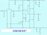
I would increase C6 to 2,2uF and C7 to 330uF, especially when the amp is playing as a subwoower amp.
For Q7 that big transistor is unnecessary, a small signal device will do the job, too.
And I would use complementary output devices.
Anyway nice design, congrats!
PS: I would increase the VAS current by R6.
A lot of conflicting opinions here indeed. Perhaps if I offer mine it might confuse, err, I mean clarify the issue:
- Keep the current mirror. Perhaps some people don't like it because the amp might have less distortion, including less of the 'nice' stuff, or perhaps it's a stability thing, since simply replacing resistor loading with a current mirror increases the gain which may decrease stability (good stablity is more important than many realize). That can be fixed with increased degeneration for the input transistors.
- You should definitely degenerate the input transistors. Without degeneration, any mismatch between the transistors will have a bad effect and the bandwidth of the input stage will be low, necessitating a larger Miller compensation capacitor. Depending on how well matched the transistors are and how fast you want the amp to be, anywhere from 22 - 470 Ohms is good.
- Similarly, you should degenerate the current mirror. You can get away without degeneration if you use a monolithic matched pair here, but even then the performance won't be as good without degeneration. I would suggest smaller resistors here, of perhaps 10-100 Ohms.
- Consider buffering the Vas with an emitter-follower. The performance increase can be dramatic, although stability becomes a little more difficult to achieve. Removing the Vas degeneration resistor at the same time can also yield a small benefit.
- Lose the diodes in the rails and use regulators instead, preferably a few volts higher than the output stage rails for maximum efficiency. It's not much more complicated than the diodes if you use IC regulators, but it works much better.
- The earlier suggestion to wrap frequency compensation around two stages is good, but there is a significant risk of instability, so I wouldn't recomend trying something like that until you are very confident with amp design.
- Bias the current source with a (non-blue) LED, 'cause they look cool😀
Mr. Evil has a lot of good suggestions that I agree wholeheartedly. My only point is to use an RC network for the first stages vs. a regulated one that Mr. Evil suggested, for simplicity.
The first stages have a steady current drain, and the ltp has good psrr to begin with. a RC network (I usually use 470ohm+220uf) will be more than sufficient to decouple them from any rail droops.
The first stages have a steady current drain, and the ltp has good psrr to begin with. a RC network (I usually use 470ohm+220uf) will be more than sufficient to decouple them from any rail droops.
Congratulation edl, you reinvent Aksa 55 in your schematic from post 24. Not real one, but with Hugh Dean words: “indicative AKSA circuit”.
Here is the link to that thread:
http://www.diyaudio.com/forums/showthread.php?s=&threadid=35899&perpage=10&pagenumber=1
Maybe that explains why Hugh is so active in this thread 🙂
Here is the link to that thread:
http://www.diyaudio.com/forums/showthread.php?s=&threadid=35899&perpage=10&pagenumber=1
Maybe that explains why Hugh is so active in this thread 🙂
edl:
thanks for the compliments
well how did you know that this beast is driving my subs😀
ok... I'll try those changes
only one thing I've only got NPN output devices, well then still the amps sounds dynamic and tight, but yet hoping that I will find enough
time and money for there complimentaries....
rgds,
hienrich
Re: Yes....reinvented the AKSA
Sorry, Carlos, what do you mean?!
destroyer X said:Or the Askaksa.
hehe
Carlos
Sorry, Carlos, what do you mean?!
Edl,
He means AKSA with reverse three letters in front - to indicate reverse engineered.......
I'm not too sure where this is headed, but I ain't tellin' nobody.....
Cheers,
Hugh
He means AKSA with reverse three letters in front - to indicate reverse engineered.......
I'm not too sure where this is headed, but I ain't tellin' nobody.....
Cheers,
Hugh
- Status
- Not open for further replies.
- Home
- Amplifiers
- Solid State
- Advanced Solid State Amp