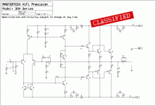
Hi Mastertech,
Nice circuit, but its a regular standard circuit not an advanced one i think..😉
You should implement emmiter degeneration resistors both at differential transistors and current mirror also. This should improve the circuit alot...
Apply your precisionist brains to get rid of capacitor in the feedback path direct couple the feedback as in high -end amps...
insert a cascode loaded differential stage to help you achieve better CMRR at high frequencies...
Try to use Deep emmiter follower stage at the output, if you really want good damping and reasonable current gain....
best regards,
K a n w a r
Looks very conventional to me.
It will work well, be absolutely reliable, and as long as it is dimensioned properly, measure very well.
It will sound accurate, have good bass, and offer excellent rail efficiency.
Cheers,
Hugh
It will work well, be absolutely reliable, and as long as it is dimensioned properly, measure very well.
It will sound accurate, have good bass, and offer excellent rail efficiency.
Cheers,
Hugh
As already said, it looks pretty conventional and with the right values should work fine. If it were mine, I would add two pole compensation, but that's just my personal eccentricity.
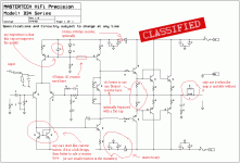
One question though. Do the diodes in the rails really accomplish much? This isn't retorical, I'm curious. The purpose is obvious (I think), but has anyone ever measured with vs. without?
One question though. Do the diodes in the rails really accomplish much? This isn't retorical, I'm curious. The purpose is obvious (I think), but has anyone ever measured with vs. without?
Hi WorkHorse ! Why ? Thanksinsert a cascode loaded differential stage to help you achieve better CMRR at high frequencies...
Hi mastertech ! If current mirror is use as a load at a input stage , Vas will often be a Darlington common emitter .Can your schematic work well
Thanks!
Lol, this design looks rather conventional, as others have said.
One point about the diodes in the rails though: When the output stage pulls the rails to droop, the diodes stop conducting and the capacitors on the other side mantain the gainstage supply voltage at a more constant value regardless of heavy output loading. This should help the paramaters stay still during heavy load conditions I should imagine.
One point about the diodes in the rails though: When the output stage pulls the rails to droop, the diodes stop conducting and the capacitors on the other side mantain the gainstage supply voltage at a more constant value regardless of heavy output loading. This should help the paramaters stay still during heavy load conditions I should imagine.
thanh said:
Hi WorkHorse ! Why ? Thanks
Hi Thanh
A cascode-connected
input circuit provides superior performance to the more common differential amplifier in the following areas:
• Better high-frequency response
• Increased high-frequency input impedance (the cascode connection eliminates the input transistor
Miller effect caused by the collector-to-base capacitance (Cob)]
• Superior power-supply noise rejection along with greater CMRR.
Because of their high output impedance, cascode-connected input differential amplifiers are
excellent voltage-to-current converters. If the circuit topology takes full advantage of the differential
input stage, the amplifier power-supply rejection ratio can easily exceed 120 dB.
regards,
K a n w a r
Thanks Workhorse ! Have you ever buil a amp like that ?
Adding cascode transistor will increase hard .
Adding cascode transistor will increase hard .
Eva said:Nice joke. 😀
I'm not sure about the ironic point, though.
😀 certainly funny, but the sad thing is... I don't think it's supposed to be a joke.

Workhorse said:Hi Thanh
A cascode-connected
input circuit provides superior performance to the more common differential amplifier in the following areas:
• Better high-frequency response
• Increased high-frequency input impedance (the cascode connection eliminates the input transistor
Miller effect caused by the collector-to-base capacitance (Cob)]
• Superior power-supply noise rejection along with greater CMRR.
Actually, I believe in the given schematic, input Cob is not a very big issue for perfectly stiff rails since you drive a BJT B-E region (plus drop on emitter resistance), this is not a big voltage swing (actually, it is substantially lower than the input signal), hence the input only sees ~Cob, not a lot of Miller effect. Things would be qiute different if the input stage was voltage driving something (perhaps a MOSFET), especially at HF...
What the input does see via Cob are power rail disturbances, and thece are easily substantially larger than the input signal. It also sees HF spray from class B output current rectification for amps with common power rails (the diode + cap thingy here will help this some). That would be point 2 above, and this is where the cascode works really well.
Mastertech is a very clever guy.... already introduced himself as a Pass fanatic.
This may be some way he found to have fun.... a trap with a sligtly modified Blameless.
Master trap maybe.ahahaha!
el gusta de polemicas Eva..... he likes to make some noise...an this is interesting too.
regards,
Carlos
This may be some way he found to have fun.... a trap with a sligtly modified Blameless.
Master trap maybe.ahahaha!
el gusta de polemicas Eva..... he likes to make some noise...an this is interesting too.
regards,
Carlos
Bottom diode (part marked by 'unnecessary') is just as necessary as the top one, and could also benefit from a small resistor in series. Discrete current mirrors without emitter degeneration are not very usefull... and the input LTP could benefit from some, too.
- Status
- Not open for further replies.
- Home
- Amplifiers
- Solid State
- Advanced Solid State Amp


