edl said:Dear Mastertech, if you dont mind... a few mods.
Edl...Would be interested what the current mirrer does to your ears.
Mastertech...What would you like us to conclude over your circuit?
😕 😕 😕
For the input differential stage, Nelson Pass, John Curl, Ernest Borbley, and several other diyAudio experts recommended resistor loads instead of a current mirror based upon their ears and product experience. You can search to confirm. Resistor loads seem even more common for JFET differential input stages.
I've only built amps with JFET inputs and low voltage power rails. For JFET differential input stages, my ears think that cascodes add noise and limit the dynamics. My experience says that matching JFETs for cascodes is very difficult and can affect distortion in stages with limited local feedback. The real world is more complicated than Spice.
I've only built amps with JFET inputs and low voltage power rails. For JFET differential input stages, my ears think that cascodes add noise and limit the dynamics. My experience says that matching JFETs for cascodes is very difficult and can affect distortion in stages with limited local feedback. The real world is more complicated than Spice.
Edl...Would be interested what the current mirrer does to your ears.
Dear Mastertech,
I've played (and still playing...) much with this amplifier globaltopology.
Due the experimentations I've found that current mirror in the LTP worsen the sonic quality of the whole amp. It gives stiff sound and become disturbing in the long run. A simple resistor gives softer and listenable sounding.
Yes, I know, it reduces THD, but I develop amplifiers for my ears, not for my measeurment gears.
If you design going to be a PA desing, then the current mirror in the LTP wouldn't be troublesome.
Best regards
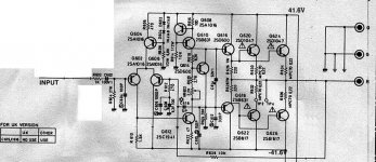
Postcript: Using the same globaltopology, my favourite realization: (let's see attachment)
The parts values and types aren't included, it develops on the concrete case. With a lot of experiment you can reach a super sounding amplifer design, with the attached schematic. Of course, it can (and should) be modified to tuning for maximal sound quality.
Attachments
Ohh... sorry, sorry guys!
I wrote
I wrote
instead of "Dear Tarasque". I think it's time to smoke one more cigarette...or drink a coffe...Dear Mastertech
very close i think...
More closer (a simple 200W/4ohm PA amplifier design):
Attachments
I thought i should my two cents. First off your Vbe multiplier needs to be adjustable so replace one of the fixed resistors wth a pot. second you need emitter resistors on the active current mirror. Third the last few schematics have shown resistive loading but have a major problem, they only loaded one of the collectors and not both. So the Vce will be different, damn body effect. BTW your circuit is very similar to my headphone amp 🙂
edl said:
More closer (a simple 200W/4ohm PA amplifier design):
Good stuff Adl
😎 😎 😎
....and it includes values as well.
What am I trying to do here...there is a X100 and Aleph4 begging to be finnished😀
Looking good!
Agree on resistor collector load for the LTP.
Agree on resistor drive for the LTP.
More attention to crossover at the output stage; see Self's Type II EF.
Now begins the difficult task of dimensioning and component choice........
Eva, Back to the Future??
Cheers,
Hugh
Agree on resistor collector load for the LTP.
Agree on resistor drive for the LTP.
More attention to crossover at the output stage; see Self's Type II EF.
Now begins the difficult task of dimensioning and component choice........
Eva, Back to the Future??
Cheers,
Hugh
Hi,
get rid of the current mirror on the LTP load.
Add Re degeneration to the LTP and Vas.
Try to reduce or eliminate the Miller compensation around the VAS and augment or replace with VAS to LTP base or output to Vas base feedback over two stages plus some comp on LTP load.
Adjustable Vbe multiplier and thermal coupling to output heatsink.
Ensure your LTP load actually balances the current in both legs of the LTP. A trimmer // to the LTP load is better than adjustable Re in the LTP emitters. Alternatively an adjustable current source for the VAS to balance the LTP currents.
I wonder if the original poster has noted that it is not possible to follow all the advice offered as some suggestions are 180 deg appart from other suggestions.
In other words, some of the advice is 180 deg "out of phase"/ Oh my!😀
Of course, he could just remove every element that someone has suggested be removed. That would be a quite a "clean" design -- nearly a blank sheet of paper.
Or how about the opposite. Make every suggested addition -- now that would be entertaining!
More seriously: A-there is more than one way to build a good or even a really good amplifier. B- There is no one perfect way to build one. C- Each of us has our favorite way of getting done. D- Ultimately you have to make you own choice build it and see what the results are.
Of course, he could just remove every element that someone has suggested be removed. That would be a quite a "clean" design -- nearly a blank sheet of paper.
😀 (been laughing for a while)
Maybe the 'advanced' stuff has something to do with the date stated in the schematic? It clearly comes from the future. 😉
I often see that diode in rail (positive rail and negative rail).
What is it's purpose? And sometimes these diodes are connected series with R (100ohm). What does these do?
What is it's purpose? And sometimes these diodes are connected series with R (100ohm). What does these do?
David,
The diode blocks rail voltage drops under heavy load, preventing bad effects on the TLP. The 100R resistor in series helps to reduce the switching noise of the diode and serves to decouple the supply, with a cap, from the main supply rail.
Cheers,
Hugh
The diode blocks rail voltage drops under heavy load, preventing bad effects on the TLP. The 100R resistor in series helps to reduce the switching noise of the diode and serves to decouple the supply, with a cap, from the main supply rail.
Cheers,
Hugh
come on guys keep the suggestions and advice coming
cause so far you've failed to note that i have declassified
this little beauty for you, some of you have commented on
the conventional architecture, guys are you kidding me
are you saying that this most conventional topology
cant make top-performance amps, well ,then please
tell me what is wrong with it if you dont want to suggest
any new improvements, thank you all for your kind suggestions
cheers
destroyer X
"
Will be a little bit better than Blameless Post #12
Good luck.
regards,
Carlos
"
you bet Carlos, it has beaten with knockouts a couple of Americans high-end amps too, blameless was not an issue
at all my friend
thanks for your positive feedback, some people cant see
what you have said either
cheers
"
Will be a little bit better than Blameless Post #12
Good luck.
regards,
Carlos
"
you bet Carlos, it has beaten with knockouts a couple of Americans high-end amps too, blameless was not an issue
at all my friend
thanks for your positive feedback, some people cant see
what you have said either
cheers
Hi, AKSA,
Thanks for the explenation😀 I'm clear about the function of the diode (and the cap, I forgot to mentioned that), but I'm not clear about the function of 100R. Is it to slow down during the charges/discharges of the capacitor?
If one is using only the diode and capacitor, without 100R, what will happen?
Thanks for the explenation😀 I'm clear about the function of the diode (and the cap, I forgot to mentioned that), but I'm not clear about the function of 100R. Is it to slow down during the charges/discharges of the capacitor?
and serves to decouple the supply, with a cap, from the main supply rail.
If one is using only the diode and capacitor, without 100R, what will happen?
 this have been rocking the whole house for almost
- Status
- Not open for further replies.
- Home
- Amplifiers
- Solid State
- Advanced Solid State Amp