Demian, do you mean isolating DAC from ADC or isolating both from the USB line?
Both actually. Typically the isolation happens after the USB interface at the I2S stage. I'm advocating for adding an extra isolated power supply and clock/data link so there is no galvanic connection between the analog side of ADC and DAC.
Just a note - FFTW is GPL licensed which means any software linking it must be GPL too.
it should not be a problem because our Cosmos_FFT.exe suppose to be free.
The open-source FFT for audio measurement would reduce the development time a lot, and everyone could make his contribution to the task improvement. I like this idea.
Time for your own thread now IVX? You are just discussing your problems and product... no?
//
//
Both actually. Typically the isolation happens after the USB interface at the I2S stage. I'm advocating for adding an extra isolated power supply and clock/data link so there is no galvanic connection between the analog side of ADC and DAC.
I tried to do this a few year ago.
The main problem was a delay (bclk-sd) in the isolation at Fs>=384.
Time for your own thread now IVX? You are just discussing your problems and product... no?
//
of course no, I have zero problems with the product, I only say that I like the GPL idea.
BTW, you asked for my sample but still didn't reply about how will you test it?
Having an APx555 and knowing how to make the usual measurements used to be somewhat of a unique selling proposition (as they call it in marketing) but that is not the case anymore.
oh, you know this one is the topic which excites me to talk about it for hours
 AP is like spiderman to me - cool, expensive, a legend but actually weak and archaic first, 10x overpriced next. For instance, AP always limits the BW in the last stage, and due to >1MHz max BW their frontend is very easy to overload with a tiny amount of a HF noise. I remember how Amir did argue me kinda he don't care about the HF noise at all because he turned On AP's 22kHz BW limit.
 One more I hate in AP, it is unreliable. I had maybe 20pcs SYS27** on my previous job, and I remember we always had something wrong with APs. We did send APs to repair for $1500 at least, even when AP needs only recover the EEPROM content. If EEPROM every year losing its data, it is not a user problem at all(actually, I believe the root cause was a poor "analog style" PCB layout).
Regarding the "legendary performance" is also a myth, my AP SYS2522 is noisy but less noisy than APx555 released 20 years later for $30000. When I switch an input impedance of AP for 300 or 600ohms I think - why not reduce a few resistors together to keep residual noise lower than .8uV? Just a few relays more and $30000 analyzer will be able to measure the noise of a cheap Cirrus CS43131 DAC(residual noise 550nVrms A-w), why not?? The same thing with THD+N, APx555 with -123-125db is way worse than modern DACs can show.
Everyone here can make for a couple of hours 1khz notch with a few res/caps and reliably overtake APx555, I think it is a shame.
Both actually. Typically the isolation happens after the USB interface at the I2S stage. I'm advocating for adding an extra isolated power supply and clock/data link so there is no galvanic connection between the analog side of ADC and DAC.
In case something like this was made, how much isolation do we need?
1. Would it be sufficient to isolate the outputs from the inputs, so with inputs still "connected" to the safety earth?
2. Assuming there are two outputs, do these have to be isolated from each other or could they be galvanically connected, as long as they are isolated from the ADC side (and the USB of course)?
I realize that the lack of isolation is a shortcoming of the RTX6001 (as you have also pointed out previously). The ground loops would be less of a problem with isolation at one end of the signal chain. But if we want to keep it (relatively) simple, how much isolation would be sufficient?
IIUC RTX has the USB fully isolated from ADC+DAC, is that correct? Thanks.
Is the ADC/DAC floating against PE?
Is the ADC/DAC floating against PE?
Last edited:
The measurement section is fully isolated from the USB.
The ADC/DAC and associated input/output amplifiers are not floating against PE.
The ADC/DAC and associated input/output amplifiers are not floating against PE.
I don't think that an isolation transformer will solve the problem (and still have a setup, which is compliant with safety standards). At least with the input voltages accepted by the RTX6001.
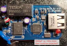
I using Hifi.me USB2 isolator $100 with AP USB interface because AP has no isolation or have but a bad one. At least Hif.me isolator with replaced 5000pF Y cap for the 50pF can work a few minutes and noticeably improves measurements related to my PC GND. There is some rare ISO SO16 chip Silana ICEUSB3 works with Ti USB HUB chip used like a buffer as I see. I asked Silana about that IC but they said it was discontinued forever and they never back with a replacement.. I hope they sold the design to somebody bigger where we'll be able to buy a similar ISO chip, probably reliable functional with 50pF.
Attachments
Is this full speed or high speed? Looking at the board, I would say it's full speed only (meaning up to 96k audio), high speed isolators are using extra logic (like FPGAs) to help negotiating the speed and direction between the two halves and, as a result, are much more expensive.
For full speed there are plenty of solutions, probably the most common one is the ADUM4160 ADUM4160 - Advice re schematic - Q&A - Interface and Isolation - EngineerZone
For full speed there are plenty of solutions, probably the most common one is the ADUM4160 ADUM4160 - Advice re schematic - Q&A - Interface and Isolation - EngineerZone
Last edited:
If you want it done right you'll probably have to do it yourself after the USB. More work, but it can be done better. In torture testing we did on a medical device we found we could not use ADuM4160 in the design. It met all specs in terms of isolation but it made USB more prone to reset in case of ESD and EMI susceptibility testing at levels beyond the standards usually go. That's if you could accept the Full Speed limitation anyway.
Thanks, I guess it would be much more effective to isolate only the ADC and DAC using standard high speed isolators (like I suppose Jen did), and leave all the XMOS s*it on the USB side. Clock switching and jitter cleaning would also be on the ADC/DAC side The XMOS evaluation board does not consider any of these isolation issues, so it will be quite some re-design.
Virtins has a high speed USB isolator (available at DigiKey) but it is, of course, expensive https://www.virtins.com/VT-USB-ISO-480.pdf
Virtins has a high speed USB isolator (available at DigiKey) but it is, of course, expensive https://www.virtins.com/VT-USB-ISO-480.pdf
Who needs freakin XMOS when you can have STM32F7 (writing this while listening to 96/32 async UAC2 on a crappy wm8994 on STM32F723Discovery) 😀
- Home
- Design & Build
- Equipment & Tools
- ADCs and DACs for audio instrumentation applications