2 K ohms as I/V is a little the limit above which I don't want to go for noise. G. chose 1k6 iirc in his last itteration, but it is also true he has much more mA outputs as he stacked several dac chip. With 2K, 1K83 (I see one vishay somewhere in Mouser), it is indeed better with the 1.1 mA of the PCM1704 or the 1 mA of the AD1862 !
1k5 works fine with AD1862 Miro's value, with the pre after, volume pot more in the twelve houts position, which I prefer btw. I willpeek the value I can find for the non inductive resistor I can find there below or equal to 2K. Never bougth at Digikey here as they are more expensive than Mouser. And the local service at Mouser France is quite good I found.
1k5 works fine with AD1862 Miro's value, with the pre after, volume pot more in the twelve houts position, which I prefer btw. I willpeek the value I can find for the non inductive resistor I can find there below or equal to 2K. Never bougth at Digikey here as they are more expensive than Mouser. And the local service at Mouser France is quite good I found.
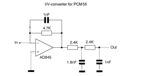
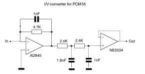
Responding to "some other op-amps" in the thread title, I've been doing some modding on my socketed chi-fi PCM56 DAC. This comes with 2 stages of NE5534 op-amps. First I removed the small cap between pins 5 and 8 on stage 1, and put in an AD845 which was an improvement and a good sound. I left the second NE5534 buffer. The sound was clean though missing some low level detail. I then took out the stage 2 NE5534, and took the output from pin 3. In this setup there was a lot more low level detail, plus good tonality on voices and acoustic instruments, but the overall sound was less clean. It sounded compressed, as if the dynamics were flattened and homogenised. This was most apparent at low volume levels.
Can you guys explain this phenomenon? What can it be attributed to? I see from following threads here that your setups don't usually include a second stage buffer, so what can be done? Maybe a better buffer? Why does a buffer make such a difference and what's the best way forward?
In this setup the DAC goes into a type 27 mesh valve stage with 100K input resistor. The DAC board uses a SPDIF input fed by a V-Link asynchronous USB/SPDIF converter. Source is a Mac Pro with archived CDs in iTunes.
Attachments

come on Grunf, let me prepare the new pcb for tha actual AD811 version, people are sending me DM asking for it !@zoom777 if you have already decided on the AD811, solder it directly to the PCB without the DIP base. You will reduce the length of the pins and improve the RF performance.I did the same because I concluded that there is no more need to test op amps until some new ones appear on the market and until then I will surely make some discrete I/V of my own, so the fun never ends.
And at the expense of fun, yesterday at Mouser I found all the tantalum resistors for Walt's shunts with which I feed the AD811 in my DAC and at the same time I make a complete Le Monstre with tantalum resistors including in the regulators. Now I've started using Vishay tanatal dividers for regulators. Only the best.
Otherwise, kudos for the work and good-sounding DAC with AD811 😉.
Come on! 😍

I would add my voice to a pcb for the AD811. That's the direction I'm going in, like many others.
I got answers to my questions above elsewhere, but if anyone has anything to add it could possibly be useful.
I got answers to my questions above elsewhere, but if anyone has anything to add it could possibly be useful.
Another vote for Silv.. ehm Donal.. aehm.. Grunf! Altogether now
Vunce made it in the AD1862 thread if you ask him by PM. AD811 pcb with Walter young reg, you are not in the obligation to popukate the reg part if you have a TSA7 regs if total cost matters.
I would add my voice to a pcb for the AD811. That's the direction I'm going in, like many others.
I got answers to my questions above elsewhere, but if anyone has anything to add it could possibly be useful.
frankly you can make it with a verroboard if you use the dip8 w/o socket, avialable at Mouser. Inductance matter you can use smd advised by G. directly soldered between the pins or a tht very close with minimum leads length. Easy to solder a Wima FKP2 in //.
You can etch where it needs grounds at the bottom of the pcb.
Another vote for Silv.. ehm Donal.. aehm.. Grunf! Altogether now
The Gulf of Naples has been renamed after a phone call by the Gulf of Leningrad ! 🤣 . It was a little too far for a "Keys Islands''Gulf !

we are talking about v2 of that very boardVunce made it in the AD1862 thread if you ask him by PM. AD811 pcb with Walter young reg, you are not in the obligation to popukate the reg part if you have a TSA7 regs if total cost matters.
What's the V 2has ? SMD ? Can be made at the bottom between the op amps legs. You can make it, it is not hard to design in 2 layers.
What I really wonder is why the design is terminated by a 49 k R shunt with few pico in // at the pcb output? I haven't understood that part ! WHat is the final output impedance of the shematic 1 ?
What I really wonder is why the design is terminated by a 49 k R shunt with few pico in // at the pcb output? I haven't understood that part ! WHat is the final output impedance of the shematic 1 ?
Last edited:
We Dalmatians would say; 'di je priša' (why the rush?) 🤣come on Grunf, let me prepare the new pcb for tha actual AD811 version, people are sending me DM asking for it !
Come on! 😍
I'm just ordering parts for the new version of the regulator so it should be ready in about 15 days. I'd like to test it first to rule out any potential problems. This time I'll go with the IXTP02N50D but any TO220 depletion will do the job. All resistors are tantalum and can be purchased from Mouser.
I'm also working on my new Le Monstre and I've had very little free time lately so everything is going very slowly.
Za hladno pivo!'di je priša'
No ban for me pls.. 🤞
The same problem happened to me the first time I used an AD811 with a NE5534 buffer, from Signetics. It played well, but the ECC88 sound was much better to me at the time, and I moved on to tubes. Now I dared to leave the AD811 without any buffer or filter behind it and that's it.Responding to "some other op-amps" in the thread title, I've been doing some modding on my socketed chi-fi PCM56 DAC. This comes with 2 stages of NE5534 op-amps. First I removed the small cap between pins 5 and 8 on stage 1, and put in an AD845 which was an improvement and a good sound. I left the second NE5534 buffer. The sound was clean though missing some low level detail. I then took out the stage 2 NE5534, and took the output from pin 3. In this setup there was a lot more low level detail, plus good tonality on voices and acoustic instruments, but the overall sound was less clean. It sounded compressed, as if the dynamics were flattened and homogenised. This was most apparent at low volume levels.
Can you guys explain this phenomenon? What can it be attributed to? I see from following threads here that your setups don't usually include a second stage buffer, so what can be done? Maybe a better buffer? Why does a buffer make such a difference and what's the best way forward?
In this setup the DAC goes into a type 27 mesh valve stage with 100K input resistor. The DAC board uses a SPDIF input fed by a V-Link asynchronous USB/SPDIF converter. Source is a Mac Pro with archived CDs in iTunes.
To begin with, try connecting the output directly via a low-value resistor to pin 6 of the AD845, and add a 47-100K to the output in parallel with some 100pF so that the op amp output is always connected to ground, although it is not necessary. This is also the practice in the vast majority of commercial devices and since the output impedance is always low it has no effect on the sound. The AD845 does not have the same current capabilities as the AD811 so I hope the next stage is high impedance.
I'm the designer of the AD845, at least I was in a prior lifetime. 😉
The AD845 can source/sink 50mA typically. It also has a pretty high standing current in the output stage, so the OL output impedance is pretty decent.
Incidentally, it was never envisaged for use in Audio, so it was never optimized for linearity.
The AD845 can source/sink 50mA typically. It also has a pretty high standing current in the output stage, so the OL output impedance is pretty decent.
Incidentally, it was never envisaged for use in Audio, so it was never optimized for linearity.
G. What would you think to make a composite with The AD811 to get-rid of the highish input resistance ?
Jfet complementary input à la EUVL with jfet opamp servo to lowish the input resistance near zero for the next dac ic stage (the op amp servo has no signature how it is used.)
Do you think it will be stable without the I K resistor after a k170/J74 input buffer stage? At 5 to 10 mA Jfet output to input before the inverted input of the AD811 ? Also the AD811 works better with source lower than 1K (AD1862 for instance is 2K R output -(don't know for the capacitance). I know the 700 to 1 K R is here for stability, but is there a way to reduce that value or get rid of it ?
Best of two world and HF spread solved at the same time by the Jfet input ? I/V made by the AD811 still ?
from the Folded Cascode CEN pdf by EUVL aka Patrick from XEN Audio:
Last edited:
Hi wynpalmer2
I'm glad you're responding in this thread. The AD845 in the DS has even lower impedance than the AD811, so I think the problem is probably in the filter between it and the buffer, or as you say, it's not optimized for linearity. With the AD811 I drive transistor amplifiers directly and in between I only have a quality audio potentiometer. By the way, the AD811 is great for an I/V stage and I'm glad Walt used it in that way too.
Igor
- Home
- Source & Line
- Digital Line Level
- AD811 as I/V stage for current DACs (and test some other opamps including Burson Audio opamps as I/V)