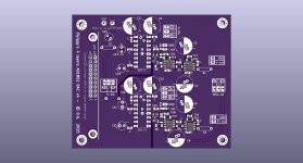
Thanks to @grunf and @miro1360 for their encouragement and support, I have incorporated the AD811 on my DAC board.
Resistors around the AD811 are Vishay tantalum. I have also included through hole pads for the IV resistor, just in case i would want to experiment with other resistors in future. I have previously used the same AD811 circult with PSU ( as an off-board IV stage, board designed by Vunce), and I love the results of what I hear. I have tried the AD844, OPA828, OPA4625-1, AD797, OPA1655 etc and a couple of discrete op amp from Burson (V6, V7). Now i am certain that I like the AD811, i have decided to finalise it on my DAC board. The Burson V7V and AD811 are very close in terms of sonic characteristics and quality. Both are great beasts. Perhaps the V7V has a slightly bigger soundstage than the AD811, with the AD811 has a slightly more forward presentation and pinpoint imaging on my PCM1704 DAC. I am not really good with words to go into intricate details and differences between the two but self experience is best for learning.


Resistors around the AD811 are Vishay tantalum. I have also included through hole pads for the IV resistor, just in case i would want to experiment with other resistors in future. I have previously used the same AD811 circult with PSU ( as an off-board IV stage, board designed by Vunce), and I love the results of what I hear. I have tried the AD844, OPA828, OPA4625-1, AD797, OPA1655 etc and a couple of discrete op amp from Burson (V6, V7). Now i am certain that I like the AD811, i have decided to finalise it on my DAC board. The Burson V7V and AD811 are very close in terms of sonic characteristics and quality. Both are great beasts. Perhaps the V7V has a slightly bigger soundstage than the AD811, with the AD811 has a slightly more forward presentation and pinpoint imaging on my PCM1704 DAC. I am not really good with words to go into intricate details and differences between the two but self experience is best for learning.


Hi Zoran,
Thanks.
Does the AD8065/66 really need 1K R serie at input ? 🤔
@zoom777 , what reg did you choose for the ad811 ? Where did you find the 1k47 tantalum ? Mouser ? I see they have 0404, 0603, few 0806 size ! Is that a 1206 casing in your's ? How much bandwith is 1k47 for the I/V, please ?
So you like it better than a op828 ? (how many volt did you try with the op828 and how did you compensate it ?).
Both ad811 and Burson V7 were benchmarked with the same dac ic and same powersupplu for both ?
Thanks
Last edited:
I promised that I would write something about my impressions of listening to the AD811. Its direct predecessor was D1Pass in my system and here I have the best comparison. The fight was long, but ultimately AD811 won. The differences are not big. What I really like about the AD811 is its wide stage, space, excellent dynamics and very accurate reproduction of small, almost invisible details in songs. It's really addictive and can show you familiar songs in a new way. Gentle hits on the cymbals or a brush on the drums - it sounds great 🙂and report why you liked it over what you listened before, please. Porn w/o explanation is less Hentaiiiiiiie ! 🙂
Ah, I have to try then...
Put it on my next Mouser with ADA4899-1 & opa891. It will stay smd though so need a radiator for smd.
If I had a differential output dac chip I would have chosen the opa1633 too, but I very don't knowif a differential op amp can be used to intput two single ended output like the ones of two AD1862 & and output theme single ended too !
I ultimatly can on my last 4 layers iteration pcb use both VFA & CFA, or direct current output to stack an opa861 or a tube with few compromise... Can surely inspire others diyers...😎
Attachments
Last edited:
@zoom777 if you have already decided on the AD811, solder it directly to the PCB without the DIP base. You will reduce the length of the pins and improve the RF performance.I did the same because I concluded that there is no more need to test op amps until some new ones appear on the market and until then I will surely make some discrete I/V of my own, so the fun never ends.Thanks to @grunf and @miro1360 for their encouragement and support, I have incorporated the AD811 on my DAC board.
Resistors around the AD811 are Vishay tantalum. I have also included through hole pads for the IV resistor, just in case i would want to experiment with other resistors in future. I have previously used the same AD811 circult with PSU ( as an off-board IV stage, board designed by Vunce), and I love the results of what I hear. I have tried the AD844, OPA828, OPA4625-1, AD797, OPA1655 etc and a couple of discrete op amp from Burson (V6, V7). Now i am certain that I like the AD811, i have decided to finalise it on my DAC board. The Burson V7V and AD811 are very close in terms of sonic characteristics and quality. Both are great beasts. Perhaps the V7V has a slightly bigger soundstage than the AD811, with the AD811 has a slightly more forward presentation and pinpoint imaging on my PCM1704 DAC. I am not really good with words to go into intricate details and differences between the two but self experience is best for learning.
View attachment 1421731
View attachment 1421737
And at the expense of fun, yesterday at Mouser I found all the tantalum resistors for Walt's shunts with which I feed the AD811 in my DAC and at the same time I make a complete Le Monstre with tantalum resistors including in the regulators. Now I've started using Vishay tanatal dividers for regulators. Only the best.
Otherwise, kudos for the work and good-sounding DAC with AD811 😉.
Hello diyiggy,@zoom777 , what reg did you choose for the ad811 ? Where did you find the 1k47 tantalum ? Mouser ? I see they have 0404, 0603, few 0806 size ! Is that a 1206 casing in your's ? How much bandwith is 1k47 for the I/V, please ?
So you like it better than a op828 ? (how many volt did you try with the op828 and how did you compensate it ?).
Both ad811 and Burson V7 were benchmarked with the same dac ic and same powersupplu for both ?
Thanks
The DAC board is currently tested on a wooden board. The PSU I used are TPS7A4701 +TPS7A3301 :
https://www.aliexpress.com/item/1005007509243183.html?spm=a2g0o.cart.0.0.386138daYEC8y1&mp=1
They may or may not be used as the final psu in my DAC chassis, but for the tests now, I am using them.
For your information, I did not use the value 1k47. I used 2k, because I can find them in Digikey.
All the resistors are 1206, so can i can solder with ease.
"How much bandwith is 1k47 for the I/V, please ?"
I am sorry i don't quite understand this question. Can you try to explain further?
The OPA828 and Burson V7 were used just like the default design of the IV on Miro's board.
No compensation was used for the two op amps above.
Comparisons were done on the same version of DAC board, same PSU mentioned above.
As an op amp IC, the 828 is very good, and in fact better than the AD797 ( with datasheet compensation).
828 actually did not disappoint me in most of the DAC. They sound open and lush, dynamic.
But the AD811 has a very good control of the music, with pin-point imaging. Subjectively, i personally feel that the AD811 is a better candidate.
In the past, I have been testing the AD811 (Vunce's board design) which has its own PSU on the board, with the other op amps.
I know that it will never be a real fair comparison unless the AD811 is powered by the same PSU and on the same layout.
Hence this version of board allows me to get closer to a fair comparison.
I should have made the board with SMD footprint for the AD811....🙂@zoom777 if you have already decided on the AD811, solder it directly to the PCB without the DIP base. You will reduce the length of the pins and improve the RF performance.
Ah sorry, I looked the wrong resistor on your picture !
The smd will be better from a point of view of passive parts layouting, but you can push higher the V with the dip and make a better decoupling of the power rail as a through hole (inductance, stray capacitance...). But indeed G. is rigth it is too fast op amp to be on a socket, mayvbe it oscilllate at high bandwith (measure between 10 Mhz to 100 Mhz perhaps).
Not sure the smd version will be happy with more than 10V cause too hot maybe... the input stage is noisy enough in the audio band.
The op828 is very analog like sound I found, but not the one I prefer. However I was said I powered it with not enough voltage (5Vdc)... could be happier nearer to its max Vdc.
Last edited:
Have you posted the schematic of the board anywhere? I am curious about the IV stage.Ah, I have to try then...
Put it on my next Mouser with ADA4899-1 & opa891. It will stay smd though so need a radiator for smd.
If I had a differential output dac chip I would have chosen the opa1633 too, but I very don't knowif a differential op amp can be used to intput two single ended output like the ones of two AD1862 & and output theme single ended too !
I ultimatly can on my last 4 layers iteration pcb use both VFA & CFA, or direct current output to stack an opa861 or a tube with few compromise... Can surely inspire others diyers...😎
@zoom777 if you have already decided on the AD811, solder it directly to the PCB without the DIP base. You will reduce the length of the pins and improve the RF performance.I did the same because I concluded that there is no more need to test op amps until some new ones appear on the market and until then I will surely make some discrete I/V of my own, so the fun never ends.
Yeah, I definitely agree with that statement 100%.
The I/V stage is the same as yours and post 1: it permits a resistor in serie between the The dac and the inverted input with the global feedback resistor//cap.
What it has in plus is at the junction of the serie input and feedback resitor there are a serie resistor and cap to ground for further tweaking compensation or passive filtering like Rutgers did with the LT1028; it can be keeped unpopulated. op 2 can be bypassed simply.
I have apiggy back diode at the output of the dac chip, both for protection and HF filtering purposes (help a little) peaks spreads .
At the output of op amp 1 there is the same output resistor then it is a buffer or a gain amp op2 at non inverted input, feedback at the inverted node (voltage follower). I will add the resistor and capacitor like in shematic 1 though (r4 & C5 to cope to G. shematic. The output resistor before the RCA is through hole, I like some choice here (carbon comp or carbon film is not noisy enough with <= 50 ohms but sounds better to my ears than metal film here. Tantalum in my experience color the sound a nice way in some I/V, but I have only experience with Takman through hole.
I don't think it is worthing to go the tht route in the feedback of speedy op amps : way too much inductance, you must stay compact like I did above. Though it is not impossible with DIP8 but then I will route it a different manneer. It is important too the ICs to be nearer to the op amps imho. Exception for the open loop ad844 and op861 that can benefit of a tht like the Rhopoint or else good tht (i likeVishay AC serie or either carbon here)
So nothing fancy but 4 layers with care to short layout, stray inductance and capacitance; 0805 decoupling for the active ic and better layout than 2 layers and also shorter with no current crossed on the I2S input. No power supply that cross the analog signals too. Digital current directed into controlled loops not to mix with Vdigital & Agnd elswhere than under the ICs. ufl input below the board, JLSOUNDS header above. The 4 layers and directed gnd loop permited a better routing of the digital inputs in a clean gnd dedicated layer splitted from the powersupply loops (5V).
Edit : for the opa828, maybe try 1n to 2nF COG // to the feedback R, or silver Mica, or styren tin foil if THT, of course FKP2 is okay too.
Last edited:
yeah but you know I have to do it, and as it works in real I didn't have to do it ! You take the shematic 1 post1 , at the junction point of R1 C1 you route a serie R then C to Gnd. After R4 on shematic 1 you add the buffer (so non inverted input, inverted input feedback to output, a voltage follower/buffer so.
It was made for a higher bandwidth and speedier op amp than the Ad811.
Rest is like the other direct JLSOUNDS/uf-l boards. The only thing is 12V ad1862 is not shared with the opa amps that have their own power plug as can be seen on the board.
What matters really is the layout and most can not be seen on the picture board.
I can make a shematic if some are interrested by a GB at low price as I don't want to publish the gerbers. But off topic there, it is dedicated to I/V op amps and third party discrete.
Last edited:
I believed naivly C5 and R5 on shematic 1 were the inputs datas of the pre or amp next stage...and were here because needed for the sim !

I made just 50 ohms controled capacitance on the board for all the signal traces with veeeeeery smal capacitance loop with the gnd layers above or below.
I made just 50 ohms controled capacitance on the board for all the signal traces with veeeeeery smal capacitance loop with the gnd layers above or below.
Last edited:
- Home
- Source & Line
- Digital Line Level
- AD811 as I/V stage for current DACs (and test some other opamps including Burson Audio opamps as I/V)