I've been laid up in bed ill this week, so not made any progress. Starting to feel a little bit better today so hopefully will get back to work on this project shortly.
A little, thanks for asking, hopefully will be back to normal soon. I have made some progress and will post some pictures of what I have done later today.
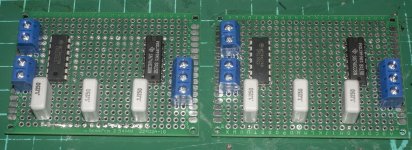
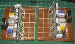
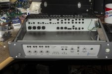
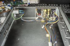
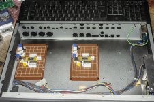
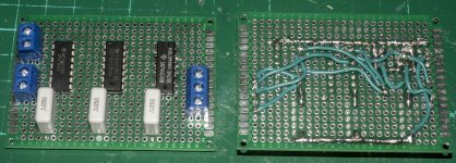
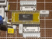
Here's some pictures of the progress I've made, I've built the logic boards, but none are 100% complete yet as I'm waiting for some parts to arrive.
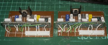
The shift register boards are a bit messy, not my best work, after I did them I wished I'd laid them out differently, but that is hindsight.
I've obtained a really nice enclosure to put it all in, I'll take some pics of that after the England vs Croatia game, which is just about to start.
The shift register boards are a bit messy, not my best work, after I did them I wished I'd laid them out differently, but that is hindsight.
I've obtained a really nice enclosure to put it all in, I'll take some pics of that after the England vs Croatia game, which is just about to start.
Attachments
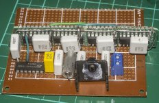
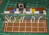
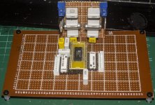
Made some further progress, so now I can start to work out the rest of the device - the receiver, digital filter(s) and the analogue output stage.
Attachments

Because of few proposed sch-s for thermometer encoder only one "working" 🙁
in sim-spice that i "tested" and will try to made some dac with that segment...
.
Some close to common-sense number of MSBs to send to Thermoter is limited to first 4 that is for 15. Advantages may be, single R value network (like fir DSD used). I think that still these Rs should be from small tolerances. But I will report and will start from worst case 1% test...
Next this midlle-complicated thermometer circuit adding some delay probably could be corrected to all other net lines?
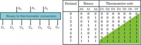
To my understanding there are no chips around which would perform "3 to 7" or "4 to 15" thermometer encoding - am I right?? At least I couldn't find any. If that is the case, the question is WHY ON THE EARTH do they not exist? I have seen the logic on a paper, which did not look much complicated...
This is simply logic digital IC that performs binarry to termomether decoding. Some DACs are already implemented circuits inside the chip.To my understanding there are no chips around which would perform "3 to 7" or "4 to 15" thermometer encoding - am I right?? At least I couldn't find any. If that is the case, the question is WHY ON THE EARTH do they not exist? I have seen the logic on a paper, which did not look much complicated...
Yes circuit does not so complicated until 4 to 15 bits but it is for say more than 4 bit... 🙁
Yes I didnt see any "compact" IC example of this type of circuit - so You should make it from logic gates...
How about making the good old voltage divider string (like a pot), giving it some stable v_ref and selecting the output with a mux? Below is one with impressive specs. No thermometer code needed and I would guess almost no current switching glitch would exist. Please note that the string could be made using quite low resistor vales so that it would look like a very low output voltage supply seen from mux - even though the mux specs indicate very low leakage.
What am I missing? Why haven't we seen such a thing so far (well, at least I haven't)
https://eu.mouser.com/datasheet/2/609/ADG726_732-1503078.pdf
What am I missing? Why haven't we seen such a thing so far (well, at least I haven't)
https://eu.mouser.com/datasheet/2/609/ADG726_732-1503078.pdf
Maybe I can layout a logic board that accept I2S?
And probably compatible with commonly-used 20Pin like Amanero and XMOS?
USB-->I2S--->Logic Converter-->Paralleled Data Bits--->DAC
And probably compatible with commonly-used 20Pin like Amanero and XMOS?
USB-->I2S--->Logic Converter-->Paralleled Data Bits--->DAC
Maybe I can layout a logic board that accept I2S?
And probably compatible with commonly-used 20Pin like Amanero and XMOS?
USB-->I2S--->Logic Converter-->Paralleled Data Bits--->DAC
I am slowly learning the terminology. Are you suggesting something like this as an example:
16 bit data --> (10 bit binary weighted) + (6 bit unary) = 10 bit + 63 bit (2^6 - 1, thermometer code) = 73 bit parallel --> DAC.
Alternatively, if 73 pins are a bit too much, how about loading 73 bit words serially into shift registers, which then put parallel out to the DAC?
I have no idea what can and cannot be done with these microprocessors like Arduino, Raspberry etc (or those you have mentioned??). Can they, for example, reverse all the bits and add 1 if MSB = 1 so we get an easy sign magnitude code? This would be one of my my dreams as well.
Thank you... You may be right. But I think one day I need to go through some trial to be convinced 😀
As we started chatting about segmentation, let me share the following idea, which does not require the thermometer code. You might have seen it though. As you see, I am willing to try something, which is not touched upon yet. In particular, it my be possible to obtain 3-5 segments (each fully decoded) and stitched together with binary weights. I tried to explain the idea with an example in # 5.
https://www.diyaudio.com/community/...r-string-selector-switch.385507/#post-7004263
This is simply logic digital IC that performs binarry to termomether decoding. Some DACs are already implemented circuits inside the chip.
Yes circuit does not so complicated until 4 to 15 bits but it is for say more than 4 bit... 🙁
Yes I didnt see any "compact" IC example of this type of circuit - so You should make it from logic gates...
@Zoran, to come back to this thermometer code issue... Have you seen any attempt which use the so called "diode matrix" (or diode ROM)? Below is an example for n = 3 and n=4 using 120 cheap diodes does not seem too crazy. The resistors could be around 5k.
Hi
For first 3 MSB (bits), You will have only 3 input to thermometer encoder and 7 outs. Not 7 inputs and 7 outputs...
For first 4 MSB (bits), You will have only 3 input to thermometer encoder and 15 outs.
...
there are some tables


For first 3 MSB (bits), You will have only 3 input to thermometer encoder and 7 outs. Not 7 inputs and 7 outputs...
For first 4 MSB (bits), You will have only 3 input to thermometer encoder and 15 outs.
...
there are some tables
Attachments
Last edited:
Thanks but when you build a segmented DAC, say for n=3 MSB, you will need to add 2^n - 1 = 7 unary pieces (see below for the generic idea). I did a sloppy job in explaining my idea. In my drawing I did not show 3 binary inputs. I have only shown 8 corresponding decoder outputs (on the left - just 1 out of 8 stuff) and 7 thermometer outputs (at the bottom). I have exemplified 3 codes from decoder output and 3 corresponding thermometer codes (black, red, blue). Let me add that on the LHS, binary input goes from 000 to 111, from bottom to top. So, the whole picture is equivalent to the table you kindly supplied above.

I eventually got my dual-AD768 DAC working where the interface is handled by a HC32F460 Cortex M4 MCU. It needs the 64pin package to have two 16bit parallel ports to talk to the DACs. I jigged the power supplies so it only needs a single 10-12V power rail. At present the MCU is doing 8X upsampling - the output filter is the next part to be added on, probably a 3rd order CLC will be sufficient.


Subjectively this dual AD768 is giving satisfying results so I've built a second prototype with the aim of playing around paralleling the two to get the noise down.
The noise specification for AD768 is rather interesting - the datasheet has this :

Footnote 7 tells us that its measured at IoutB so if the two balanced outputs are taken then we should see 3dB improvement assuming the noise isn't correlated between IoutA & B. Also of note is the condition DB0-DB15 high, which is the maximum output. Normally noise for DACs is given at digital zero, not at maximum output. As R2R DACs are multipliers of their reference current it seems reasonable to me to infer that if the noise comes from the reference then the noise at digital zero is going to be lower than at full scale. The 3nV figure integrated in a 20kHz BW gives 0.4uV noise and the (single-ended) signal's 1V p-p or 353mVRMS giving 119dB SNR. Not too shabby at all, especially as it seems to be an upper bound.
AD1862 is the only DAC chip I've come across that shows its output noise as a function of code, and frequency :

The noise specification for AD768 is rather interesting - the datasheet has this :
Footnote 7 tells us that its measured at IoutB so if the two balanced outputs are taken then we should see 3dB improvement assuming the noise isn't correlated between IoutA & B. Also of note is the condition DB0-DB15 high, which is the maximum output. Normally noise for DACs is given at digital zero, not at maximum output. As R2R DACs are multipliers of their reference current it seems reasonable to me to infer that if the noise comes from the reference then the noise at digital zero is going to be lower than at full scale. The 3nV figure integrated in a 20kHz BW gives 0.4uV noise and the (single-ended) signal's 1V p-p or 353mVRMS giving 119dB SNR. Not too shabby at all, especially as it seems to be an upper bound.
AD1862 is the only DAC chip I've come across that shows its output noise as a function of code, and frequency :
- Home
- Source & Line
- Digital Line Level
- AD768 as audio DAC