Any one tried Single Supply BD?😕
I am currently using bipolar supply for BD experiments. Dont want to use an OPAMP for converting differential to single ended feedback. Currently running separate feedback loops accross filter, direct to Quad input differential comparator with Av[gain]=4😉
I am currently using bipolar supply for BD experiments. Dont want to use an OPAMP for converting differential to single ended feedback. Currently running separate feedback loops accross filter, direct to Quad input differential comparator with Av[gain]=4😉
I think common mode voltages are already represented graphically inthat post.🙂
Then I think that already presented histograms were built NOT for the common mode voltages 🙂
Then I think that already presented histograms were built NOT for the common mode voltages 🙂
I wasnt talking about common mode histograms, i was talking about common mode graphically represented wave forms.🙂
Cool pictures! 🙂
Could you please build these black&white 'hystograms' for common mode voltages too?
Many thanks!
I wasnt talking about common mode histograms, i was talking about common mode graphically represented wave forms.🙂
So I was asking about histograms for common mode voltages, and you have answered, that common mode voltage waveforms are already presented... 🙂 Thanks, but I have seen it too 😉
Last edited:
Any one tried Single Supply BD?😕
I am currently using bipolar supply for BD experiments. Dont want to use an OPAMP for converting differential to single ended feedback. Currently running separate feedback loops accross filter, direct to Quad input differential comparator with Av[gain]=4😉
I use single supply for BD, but it's floating. I use OPA to make the difference signal, so this is not helpful for you.
Cool pictures! 🙂
Could you please build these black&white 'hystograms' for common mode voltages too?
Many thanks!
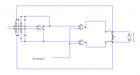
You didn't ask me, but it must be like this:
An externally hosted image should be here but it was not working when we last tested it.
If you don't like a differnetial amplifier in the feedback path then you'd have to make a differential forward path.
Regards
Charles
Regards
Charles
You didn't ask me, but it must be like this:
Thanks Pafi! 😉
BTW, which software did you used to build it?
If you don't like a differnetial amplifier in the feedback path then you'd have to make a differential forward path.
Regards
Charles
Charles,
I think using fully differential feedback will solve it, Differential IN and Diffrential OUT.🙂
regards,
Kanwar
I use single supply for BD, but it's floating. I use OPA to make the difference signal, so this is not helpful for you.
Outputs are floating or supply rails are floating?
Outputs are floating or supply rails are floating?
Both! 🙂 This way it can continue operation with one short to ground.
Thanks Pafi! 😉
BTW, which software did you used to build it?
You're welcome!
I used Paintbrush. 😀 I deduced it from the other histograms using mathematical rules, but at -1 dB modulation index I partly checked it with Tina also. I don't now what could be the original software.
Both! 🙂 This way it can continue operation with one short to ground.
You mean grounded bridge?
There can be anything. Fault, intentional grounding, or someone wants to tie in bridge the amps.
In an instrument I had to ground one of the outputs (but bridge was needed because of DC current requirement).
In an instrument I had to ground one of the outputs (but bridge was needed because of DC current requirement).
There can be anything. Fault, intentional grounding, or someone wants to tie in bridge the amps.
In an instrument I had to ground one of the outputs (but bridge was needed because of DC current requirement).
Aahh....Got it, they are just floating so you can connect them anyhow🙂
I think Kanwar is talking about what is described in Bruno's paper (which was mentioned some posts before) and not some three-state amp that is using an "open" state.
This has one advantage: The apparent switching frequency and also the actual sampling frequency is twice as high for a given carrier frequency when you use a carrier-based amp. Therefore you can use more loop gain.
Regards
Charles
Hi Charles,
Now thinking of incorporating a fully differential IN-OUT opamp in frontend to make a balanced BD modulation, without using a separate inverter.
Regards,
Kanwar
Attachments
1.)
Congratulations to not using a differetial amplifier in the feedback path but using a differential forward path instead.
2.)
You could also do the same thing with two "normal" OP-AMPs instead of the fully differential one but you would have to take care of possible offset problems.
Regards
Charles
Congratulations to not using a differetial amplifier in the feedback path but using a differential forward path instead.
2.)
You could also do the same thing with two "normal" OP-AMPs instead of the fully differential one but you would have to take care of possible offset problems.
Regards
Charles
Thanxz Charles,
I have constructed a discrete differential opamp for this very thing actually. Its using diamond differential high slewrate input stage with matched transistors co-packs.
I am just thinking if single supply option could be used with the full bridge output. I think it can be done, but have to see how it goes with common mode input voltage range of the discrete opamp. I will also try this with differential chip opamp also and see for any difference in performance exists or not, there is one Vcom pin incorporated in these opamps, might be helpful in setting the offset of output at certain operating potential.
http://focus.ti.com/lit/an/sloa099/sloa099.pdf
regards,
Kanwar
Last edited:
There can be anything. Fault, intentional grounding, or someone wants to tie in bridge the amps.
In an instrument I had to ground one of the outputs (but bridge was needed because of DC current requirement).
Sounds like something I 'invented' 2 years ago. Intersting.
I think it can be done, but have to see how it goes with common mode input voltage range of the discrete opamp.
It is actually commom mode input that I meant when I wrote about offset ... Think it is time for a holiday.....
Regards
Charles
- Status
- Not open for further replies.
- Home
- Amplifiers
- Class D
- AD Vs BD Modulation in Class-D