Now that a psu is on the way,Can anyone with a simulator tell me what the input impedance of the input buffer is? And is it adaptable?I would prefer around 50k.
The same goes for the ouput impedance except i would like that as low as possible, 600r or lower.
kro5998.
The same goes for the ouput impedance except i would like that as low as possible, 600r or lower.
kro5998.
Input imedance is user defined by R13 in the single ended mode.
It's touched on briefly in the manual, I'll try to flesh it out a bit. I'll need a little help on balanced.
It's touched on briefly in the manual, I'll try to flesh it out a bit. I'll need a little help on balanced.
Thanks Bob, with the figures quoted, you get less influence of your interconnects provided the output impedance of your pre-amp is low. (i don't want to start an interconnect discussion).
kro5998
kro5998
According to the datasheet, the OPA12134 has an output impedance of 0.02 ohms or less in the audio band at unity gain, like the output buffers. There is a spot for a resistor (normally 100R) between the buffer and output connections. You can jumper it if you like, but sometimes capacitive cables can cause oscillation without it.
Agreed, interconnect discussion should be in its own thread.
Agreed, interconnect discussion should be in its own thread.
kro5998 said:37 volts is about the maximum what most regulators can handle.
78XX or 79xx can't.Lm317/lm337 can just handle it but you will be dissipating a lot of heat.You will get better reliabillity whit a separate supply.
kro5998
Is it not the difference between input and output that may be up to 40 Volts? If you have 60 V ahead of the regulator you can have a maximum of 20 V after it.
Provided you lift the reference as well then there is no problem.Still it would be better to use a separate supply.
UPS has the boards within 150 miles of me, but work is taking me out of town for a few days. I should be able to get the boards shipped Monday or Tuesday next week. There are only 63 packages to send (before traveling again) 😱
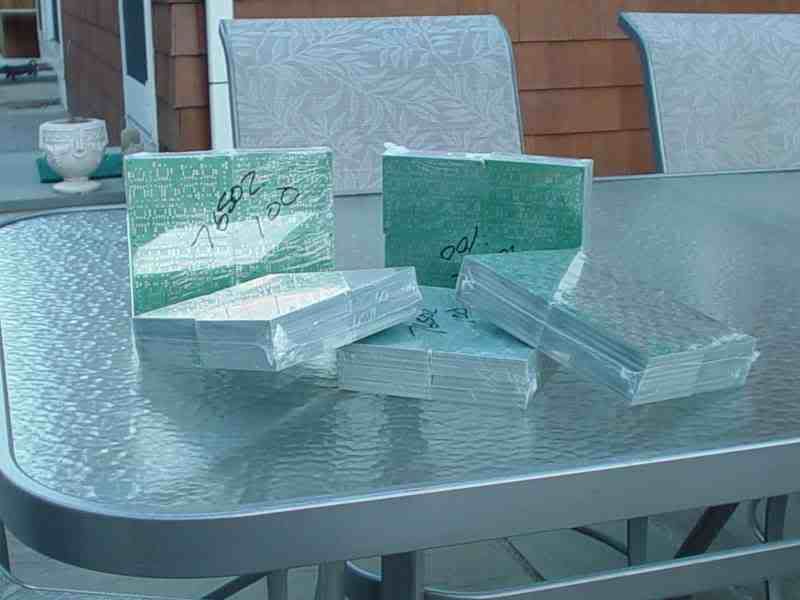
The Boards are IN!
They look great, I'll borrow a camera and post pictures tomorrow or Friday.
I'll pack them up this weekend and ship to all who have paid on Monday or Tuesday.
They look great, I'll borrow a camera and post pictures tomorrow or Friday.
I'll pack them up this weekend and ship to all who have paid on Monday or Tuesday.
Yes that's true. You can also have 197 volts in and 160 volts out. The only trouble with this is short circuit conditionsRogerGustavsson said:Is it not the difference between input and output that may be up to 40 Volts? If you have 60 V ahead of the regulator you can have a maximum of 20 V after it.

KRO wrote
Hi Kro,
Your time will be well rewarded. It's excellent!
If you like I'll be happy to advise you or even to perform measurements for you (I live near Maastricht). Perhaps we can join forces. I'm not much of an electronic expert, and I guess you are.
Perhaps you (or anyone else) are interested in the design process I developed (I'm still in the middle of it, but you'll get the idea). The zip file is too large for this forum, so send me a mail if you're interested.
Greetings
Dick
I am at the moment starting to figure out speaker workshop but i am always short of time.
Hi Kro,
Your time will be well rewarded. It's excellent!
If you like I'll be happy to advise you or even to perform measurements for you (I live near Maastricht). Perhaps we can join forces. I'm not much of an electronic expert, and I guess you are.
Perhaps you (or anyone else) are interested in the design process I developed (I'm still in the middle of it, but you'll get the idea). The zip file is too large for this forum, so send me a mail if you're interested.
Greetings
Dick
Bob, I'd like to volunteer as a novice reviewer of the manual.
If you send me the latest draft and supporting material (spreadsheets?) I'll work through it this weekend.
If you send me the latest draft and supporting material (spreadsheets?) I'll work through it this weekend.
Here they are. My camera doesn't do macro, so I'll slap it on the scanner when I get home. I've started packing up.
Yes, the 100 on the packs means 100 boards.
Yes, the 100 on the packs means 100 boards.
I was asked in the OPA2134 buy thread if I would consolidate orders for overseas shipments for opamps, PSU boards/kits, etc. and filter boards.
For those who would like to consolidate their orders for opamps, filter boards, heat sinks and psu boards/kits into one package, let me know. I will calculate postage and let you know what total shipping costs will be. There is a risk that it will be higher than a few smaller flat rate envelopes. I will NOT ship transformers in an envelope.
Within the US there is the flat rate box for around $8.50 (check the website), so you might save a little.
I have all paid filter boards wrapped and in envelopes waiting shipping labels/postage. Unless I hear from you by noon EST (GMT-5) Sunday March 26th that you want me to hold your order, I will ship it Monday.
There are quite a few more boards requested than will be left over and I am a glutton for punishment. I just opened up round two of the filter board buy. Sign up on the wiki.
Perhaps off topic:
Has anyone experience with the implementation of notch filters?
Is it all right to put such a filter in the feedback loop of the LP or HP section? According to Spice it should work. Does it in practice?
Has anyone experience with the implementation of notch filters?
Is it all right to put such a filter in the feedback loop of the LP or HP section? According to Spice it should work. Does it in practice?
It works but I think you will miss the Q setting....
Here are the measurements I did for my first filter prototype for an other project using both the NE5532 and the OPA2134
\Jens
Here are the measurements I did for my first filter prototype for an other project using both the NE5532 and the OPA2134
An externally hosted image should be here but it was not working when we last tested it.
An externally hosted image should be here but it was not working when we last tested it.
An externally hosted image should be here but it was not working when we last tested it.
\Jens
Hold the phone....
I just realized that while the circuit will work electrically it is not going to be possible to determine its frequency characteristics because of the frequency dependant feedback.
Only if you remove the EQ frequency far away from the filters slope are you going to be able estimate the Q and fn of the filter.
If you look in my manual of the active filter one you will find a transfer function for the Sallen and Kay topology with gain. In this transfer function you will need to change K from a constant to a freq. dependant function and thus creating a fourth order function. Now it gets tricky……..
Use the equations from the K=1 section to calculate the filter components and then calculate the needed EQ parts…. Insert the whole thing into the modified transfer function to find the total freq response.
\Jens
- Status
- Not open for further replies.
- Home
- Group Buys
- Active filter board GB