I don't have a quote from TI yet. Budgetary price is $1.10, but they might charge a bit more for someone not likely to be a repeat customer
Bob, Just realised I can wait for most of them. Do we need to hit 1000 to get them from TI ?
Is it OK if I add a column to your table for a 01Apr EU buy ? (just getting to 100 gives the most significant price break)
Is it OK if I add a column to your table for a 01Apr EU buy ? (just getting to 100 gives the most significant price break)
Well, we are now just 30 short of 1000 ..... 😀
If needed, we could all take 2 extra. Then were there.
Harry
If needed, we could all take 2 extra. Then were there.
Harry
Hi there. Bob, I sent money via paypal, but didn't know how to change the Wiki table, and didn't want to mess anything up.
I'm happy to wait, I need all the time to work out how it all fits together! I hope they come with instructions for muppets!
I'm happy to wait, I need all the time to work out how it all fits together! I hope they come with instructions for muppets!
harryeng said:Well, we are now just 30 short of 1000 ..... 😀
If needed, we could all take 2 extra. Then were there.
Harry
I just added 10 to my order so....were within 20!!!!!!
Mike
I just added 50 OPA, I would wait, but it hardly seems worth the difference to me. Overall its significant, but to the individual, doesnt' seem like much. I'm sure fresh ones sound better though
jimbo1968 said:Bob, Just realised I can wait for most of them. Do we need to hit 1000 to get them from TI ?
Is it OK if I add a column to your table for a 01Apr EU buy ? (just getting to 100 gives the most significant price break)
No problem jimbo - I don't own the WIKI.
BobEllis said:No problem jimbo - I don't own the WIKI.
No, but it's looking like you own the OpAmp group buy
😀 and I didn't want to poach your customers.
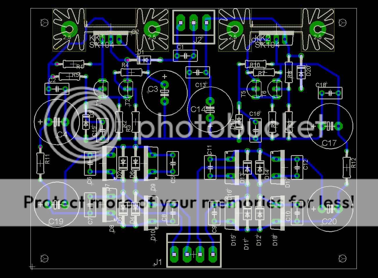
Not a Jens board design, but a power supply that should serve a variety of needs.
positive and negative regulators on one 80 x 100 mm board
Options of plain or fancy diodes, CRC filter.
The regulator portion is basically teh same as Pass used in the A75, with the addition of a capacitor on the zener. Adjustable voltage out by swapping resistor values.
Space for large heat sink
Comments/ interest? about $6 at 100 pieces.
Bob,
I will be happy to clean up the board for you...
Tomorrow is friday, and I might have some time on my hands 😉
\Jens
I will be happy to clean up the board for you...
Tomorrow is friday, and I might have some time on my hands 😉
\Jens
Jens, You've got mail.
I added a waiting list signup section on the WIKI. Priority will be based on when I receive an email expressing interest the wiki will test interest in another run of boards after the safety stock is exhausted.
I'll set up a psu GB wiki this weekend. It will include the option to include a parts kit. The parts aren't terribly expensive, but a kit would be convenience rather than a money saver.
Anyone want to do a GB for OPA2134s? We've got interest in well over 1000 pieces.
BobEllis said:Jens, You've got mail.
Anyone want to do a GB for OPA2134s? We've got interest in well over 1000 pieces.
Hi Bob, I would be interested in 4-6 PS boards. I would offer to help out on the GB for the OPA's but I am so rural that I have to drive 5 miles just to get to my P.O. box. I say this because I am blown away by your and Jens effort with this GB and want to show my appreciation.
Stan
Hi Bob,
Will you post the schematic for the V reg. PCB?
Does it use fixed or adj 3 terminal regs?
Is there any advantage for discrete diodes on the AC to DC converter?
Thanks,
John
Will you post the schematic for the V reg. PCB?
Does it use fixed or adj 3 terminal regs?
Is there any advantage for discrete diodes on the AC to DC converter?
Thanks,
John
If the order is to TI, do they sell in lots other than 1000?
i.e. do we order 1000 or 2000, when we need 1xxx?
i.e. do we order 1000 or 2000, when we need 1xxx?
I'll post a schematic once it gets cleaned up a bit. I mucked around with various ideas until the wee hours this morning and it is not well organized.
It is a completely discrete regulator, no three terminal devices. It uses a BJT pass device like the MJE15030/31 controlled by a differential pair referencing the output to a zener or other voltage reference.
If you look at www.passdiy.com the basic regulator schematic is as used in the A75 (see page 1 of A75 part 2 ). I don't use the voltage doubler part of the supply and have added a cap across the zener to minimize noise.
The output voltage is set by the value of the zener and the values in the voltage divider in the feedback section. I've used this topology for anywhere betwen 10V and 65V output.
Some people prefer discrete rectifier bridges, especially when made from high speed soft recovery devices like the MUR820, so I provided that option. Pass Labs decided to use a similar type of rectifier in the X.5 series. You can also use the $.06 1N4007 if you don't want to spring for the MURs
I included a CRC section to allow the raw DC supply to be smoother before the regulator stage.
I'm looking forward to the polish that Jens may put on it.
- Status
- Not open for further replies.
- Home
- Group Buys
- Active filter board GB