Bob, since you know a lot about filters(and i don't) i have a few questions.
After studying the filter layout i noticed that the All pass and the EQ sections are fully independant.Shouldn't they be inserted after the LP or HP sections and before the outputbuffer? If so can i use a simple piece of wire to connect them without ill effects?
My speakers are build in separate enclosures.One for the bass speaker and one for the mid/high speakers (passive filter)
I am planning to use the filters as 2 way fourth order filters.
For the LP filter i might want to use the linkwitz transform section to raise the low end.As far as i now this is no problem.
For the HP section i might need the all pass section for phase compensation.
Since i use separate enclosures i need baffle step compensation for both the LP an HP sections.Can i modifiy the EQ sections for baffle step compensation?(perhaps bridging r22/r17).
Kro5998
Kro -
The "extras" are that way so you can put them where needed. Maybe your woofer has a dip in response in the pass band and the usual breakup peak. You can put both EQ sections in the woofer signal path. Yes, a piece of wire is fine, as long as it is silver and costs at least $400 per inch. Just kidding - plain old hookup wire is fine.
You probably really only need one baffle step. You set it up to take care of the high baffle step and adjust the level of the woofer section to match.
If you are crossing over close to the BSC center, you may not even need to apply ANY BSC - try boosting the level of the woofer relative to the mid. While it may not be perfect, you'll be awfully close.
If you use the input buffer for BSC, you apply the shelving function to both high pass and low pass sections. So if the baffle step spans the crossover, both drivers are affected by the BSC.
For a dual BSC application, (Dipole EQ users take note, too.) you can use one of the EQ sections. Notice that the buffer (IC1A) looks an awful lot like the input buffer. Leave out R17, C8 and C13. Run a wire from JP6 pin 1 to the R22 end of R17 and you've got another BSC stage. Run a wire from the other end of R17 to ground to prevent IC1B from doing funky things that might have an impact on the rest of the circuit.
If you don't need the all pass (like with separate woofer and mid cabinets that can be physically aligned) you can use that for another shelving low pass section by omitting C7 and lifting the input end of R3 and connecting it to ground. Same as the input buffer, just drawn differently
I'm working up a manual that will outline this and other things you can do without even cutting traces. It will also include a couple of design examples to try to make the process less mysterious.
I've dropped a lot of stuff in Jens' lap with the PSu and reviewing the first part of the manual. If anyone is near Jens, drop by and buy him a pint or two.
The "extras" are that way so you can put them where needed. Maybe your woofer has a dip in response in the pass band and the usual breakup peak. You can put both EQ sections in the woofer signal path. Yes, a piece of wire is fine, as long as it is silver and costs at least $400 per inch.
Just kidding - plain old hookup wire is fine. You probably really only need one baffle step. You set it up to take care of the high baffle step and adjust the level of the woofer section to match.
If you are crossing over close to the BSC center, you may not even need to apply ANY BSC - try boosting the level of the woofer relative to the mid. While it may not be perfect, you'll be awfully close.
If you use the input buffer for BSC, you apply the shelving function to both high pass and low pass sections. So if the baffle step spans the crossover, both drivers are affected by the BSC.
For a dual BSC application, (Dipole EQ users take note, too.) you can use one of the EQ sections. Notice that the buffer (IC1A) looks an awful lot like the input buffer. Leave out R17, C8 and C13. Run a wire from JP6 pin 1 to the R22 end of R17 and you've got another BSC stage. Run a wire from the other end of R17 to ground to prevent IC1B from doing funky things that might have an impact on the rest of the circuit.
If you don't need the all pass (like with separate woofer and mid cabinets that can be physically aligned) you can use that for another shelving low pass section by omitting C7 and lifting the input end of R3 and connecting it to ground. Same as the input buffer, just drawn differently
I'm working up a manual that will outline this and other things you can do without even cutting traces. It will also include a couple of design examples to try to make the process less mysterious.
I've dropped a lot of stuff in Jens' lap with the PSu and reviewing the first part of the manual. If anyone is near Jens, drop by and buy him a pint or two.
The calculated baffle step for the woofer is 520Hz and for the mid it is 820Hz so not close enough.Besides that i really wanted to cross over in the 300Hz region to let the mid's over to one speaker.
I am at the moment starting to figure out speaker workshop but i am always short of time.
kro5998
I am at the moment starting to figure out speaker workshop but i am always short of time.
kro5998
Are those the center frequencies or the beginnings of the steps?
If 820 is where the transition starts, then you'll be fully transitioned an octave lower, 410 Hz. With a 300 Hz. XO, the woofer should need no BSC.
Do a search on the "Edge" baffle diffraction simulator. You can model an enclosure that looks like yours and see where the step is. It allows you to enter where the compensation starts and stops and will show you its impact. Nice tool. The program uses a different topology to handle BSC, but the acoustics are right.
You can also use BDS (baffle Diffraction Simulator). It is a bit more powerful than the edge, but the learning curve is so steep it makes speaker workshop seem intuitive. (I've looked at it a few times, but haven't figured out how to make it work for me)
Sorry Bob, another question from someone without a full grasp of what's going on.
I am going to be running a set of Tannoy coincident 12's actively. The tweeter is going to require a notch at about 3k and a rise starting at about 5k all the way out to 20k. Do you think I can achieve something like this with this Xover and its eq abilities. I hope so or it's Berhinger for me (I keep saying that )
)
regards...
I am going to be running a set of Tannoy coincident 12's actively. The tweeter is going to require a notch at about 3k and a rise starting at about 5k all the way out to 20k. Do you think I can achieve something like this with this Xover and its eq abilities. I hope so or it's Berhinger for me (I keep saying that
)regards...
the notch is no problem.
You may be able to solve you boost requirement by making a peak filter out of the other EQ section centered near 20 Khz. can you post a FR curve? You'll adjust the peak height and center to get the curve you need in teh affected area.
You may be able to solve you boost requirement by making a peak filter out of the other EQ section centered near 20 Khz. can you post a FR curve? You'll adjust the peak height and center to get the curve you need in teh affected area.
I have no curve to post just info from other tannoy users. From what I understand it's very similar to what would normally be needed for a CD horn..the need for a rise???!?
Thanks..the 20k boost may be a starting point🙂
just info from other tannoy users. From what I understand it's very similar to what would normally be needed for a CD horn..the need for a rise???!?Thanks..the 20k boost may be a starting point🙂
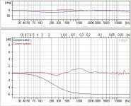
actually. here ya go: black is un-eq'd. The others are what I'm after. Those are 3dB steps...
This, care of: http://www.hilberink.nl/codehans/tannoy86.htm
where there are also schematics offered!
This, care of: http://www.hilberink.nl/codehans/tannoy86.htm
where there are also schematics offered!
Attachments
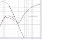
That response looks like the 3 KHz notch is doing it all. Model it in a circuit simulator and you'll see that a notch affects quite a wide range. A combination of notch filter and attenuation and you should achieve your goal.
Thanks a lot!
Good observation, and now that you said that I can't help but agree with you. I think it could be as simple as that🙂
Good observation, and now that you said that I can't help but agree with you. I think it could be as simple as that🙂
That looks pretty good, nothing the board's EQ cant fix. Of course working with measured response is better. SW is well worth the time it takes to learn how to use it.
A power supply question.
My amplifier has +/-37V rails. Can I just use +/-15V regulator chips to get my crossover supplies?
My amplifier has +/-37V rails. Can I just use +/-15V regulator chips to get my crossover supplies?
Thinking about it, if you have the chips, I would use another pre regulator stage, set at, say, 25V. It will improve the performance and spread the heat around a little
- Status
- Not open for further replies.
- Home
- Group Buys
- Active filter board GB