AndrewT said:Hi,
are you correctly terminating the unused input?
No. Only one input used at testing.
Will be used with balanced preamp.
Hi,
if you feed an unbalanced signal into one pin of a balanced input, then the other pin must be terminated to allow the amp to correctly set the gain and input conditions.
When you feed both pins with a balanced signal then the source resistances (Rs+Rs) terminate both pins for you.
if you feed an unbalanced signal into one pin of a balanced input, then the other pin must be terminated to allow the amp to correctly set the gain and input conditions.
When you feed both pins with a balanced signal then the source resistances (Rs+Rs) terminate both pins for you.
Component values...
Now I got 2 pcs of filter boards, and one PSU, and I am now looking into ordering the right remaining parts....
I've been looking into this with the help of the "active_filter_four.xls"-file, but I have noticed that the values I get here is not the same as when calculated with the Linkwitz calculator from Sound Weshost (esp-lr12.exe).
seems like the latter is build with C and 2C (or R and 2R...)in some sort of cascaded Butterworth configuration, while this approach uses the same values in all capacitors..(resistors)..!?
Can someone please elaborate on this ?
PS: Thanks to novec for sharing (selling..) his "spare" parts with me !...🙂
Lyra
😕
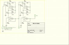
This board's filter topology is a little different than the one that the ESP calculator uses. These filters (and the spreadsheet) are set up as equal component value filters while ESP uses unity gain topology.
Notice the connections at the output of each opamp. These boards use a pair of resistors at the output to set the stage's gain (and Q) while the ESP filter connects the output of the opamp directly to the negative input. Q is set by the component values.
You can use the ESP calculated values by jumpering the appropriate resistor in the gain setting pair and omitting the other. The advantage of equal component values is that you can buy more of a single value cap and match more easily, as well as possibly save some money.
BobEllis said:This board's filter topology is a little different than the one that the ESP calculator uses. These filters (and the spreadsheet) are set up as equal component value filters while ESP uses unity gain topology.
Notice the connections at the output of each opamp. These boards use a pair of resistors at the output to set the stage's gain (and Q) while the ESP filter connects the output of the opamp directly to the negative input. Q is set by the component values.
You can use the ESP calculated values by jumpering the appropriate resistor in the gain setting pair and omitting the other. The advantage of equal component values is that you can buy more of a single value cap and match more easily, as well as possibly save some money.
Thanks....this was somewhat educating 🙂
-and by this...the sound will be equally good no matter what topology I choose !???

-what would the best Q value of this filter be ??? (straight 24 dB rolloff both ways at aprox 80 Hz)
-what Q value would correspond to the Unity Gain topology like ESP ?
Lyra
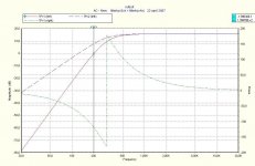
For a straight electrical Linkwitz Reilly you want a total Q of .5. If a 12 dB/octave filter set the filter Q to .5, if a 24 dB filter set each section to .7 because the total Q is the product of the filter sections' individual Qs.
Your actual Q should be whatever it takes to meet our target response with the drivers chosen.
Your actual Q should be whatever it takes to meet our target response with the drivers chosen.
Capacitance values...
In the manual it is stated:
<...Practically, You can use any value between 10 and 47 nF...>
-Does this mean that I should avoid using 68nF or even 100nF ?
(the latter is somewhat big compared to the footprint on the board, but it might go !?, but 68nF is just as big as the 47nF (MKP1837))
I kind of like the idea of using aprox 20-22k resistors rather than the somewhat larger values a 47nF cap requires...and...I got some 68nf/ 100nF laying around....
Lyra
That should work fine if they fit. The tight tolerance caps I have are fairly big, which lead to the "practical" recommendation. Some loose tolerance caps are smaller, but be careful to select them for accurate values. I have used >100 nf caps where appropriate.
OK....
Thanks, then I just have to choose between using my existing 100nF with 22k resistors, or order some new 47nF, and use 47k resistors...the latter are obviously easier to fit on the board.....but....will see 🙂
Lyra
Thanks, then I just have to choose between using my existing 100nF with 22k resistors, or order some new 47nF, and use 47k resistors...the latter are obviously easier to fit on the board.....but....will see 🙂
Lyra
Hi,
I have 150nF and 300nF fitted to the unity gain board specifically to keep the resistor values down.
I selected 100nF and 47nF and placed them on both sides of the pcb using the untrimmed pins on the reverse side to add parallel caps to give the required values.
I try to keep the resistor values between 7k5 and 12k.
But using turnover frequencies below 150Hz forces compromise.
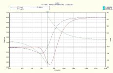
I think it may be something silly like providing a power connection for the opamps. I remember one free sim I used did something like that when I forgot power.
5spice
Thanks bob but according to the helpfile the linear op-amp symbol doesn't need a power supply.
I exchanged one linear op-amp with a OP27A for comparison and added a positive and negative supply.
The results are exactly the same.
Does anybody have a clue what i'm doing wrong?
kro5998
Thanks bob but according to the helpfile the linear op-amp symbol doesn't need a power supply.
I exchanged one linear op-amp with a OP27A for comparison and added a positive and negative supply.
The results are exactly the same.
Does anybody have a clue what i'm doing wrong?
kro5998
Hi,
R14 & R19 are connected in an unusual arrangement.
The unity gain input is normally tapped off from the output of the filter stage but you are showing it from the inverting input.
Are you aiming for Butterworth or Linkwitz Reilly?
The feedback resistors should be lower value to match the impedance seen by the non-inverting input. R14//R19=R7 & R15//R20=R9.
16db gain from 2stages is too high. It should be 8.2db or less.
Andrew,
Jens took the output of the filter stage from the negative input to attenuate the signal by the amount of gain in the equal component value Sallen-Key section. This allows varying the Q of each section without altering the crossover frequency or having to worry about overloading the following stage when using higher Q sections. I've sound this arrangement particularly useful when making Cauer filters.
Jens took the output of the filter stage from the negative input to attenuate the signal by the amount of gain in the equal component value Sallen-Key section. This allows varying the Q of each section without altering the crossover frequency or having to worry about overloading the following stage when using higher Q sections. I've sound this arrangement particularly useful when making Cauer filters.
- Status
- Not open for further replies.
- Home
- Group Buys
- Active filter board GB